|
philips mi 36
Genre: Enclosed Horizontal Traverse Low Pressure Sodium Lantern
The low pressure sodium discharge lamp was developed by Philips in 1932. After two successful trial installations
(including the first low pressure sodium installation in the UK along the Purley Way, Croydon) the first commercial installation
was installed by Liverpool Council in 1933 using specially commissioned lanterns from Wardle.
The development of lanterns continued through the 1930s and accelerated when it was determined that the lamp’s brightness and
its long length made it less susceptible to glare. Lanterns with bare bulbs suspended over an overhead reflector (the so-called "seagull" lanterns)
quickly followed. Glass manufacturers were initially slow as the first plate refractors for low pressure sodium lamps didn’t appear
until the end of the decade.
The advantages and disadvantages of low pressure sodium were readily debated, especially when an alternative (the medium and high
pressure mercury discharge lamp) was also available. The monochromatic light was considered especially useful for arterial
and traffic routes, the lamp’s shape cast a wide beam across the road surface, the light was also considered more penetrating
in foggy conditions and it was the most efficient light source being manufactured. However, the light was also considered
inappropriate for high streets, promenades, civic areas and residential streets and so some lighting engineers
restricted its use to traffic routes only. Therefore low pressure sodium became known as "the drivers’ lamp."
The arrival of plate glass refractors resulted in large lanterns made of metal frames enclosing heavy glass sheets.
These bulky lanterns continued to be made into the 1950s until being usurped by lanterns with plastic bowls and
machined or moulded plastic refractor plates. The lanterns were still large; the size dictated by the bulky
control gear, but their design and construction was becoming simpler.
The 1950s and 1960s saw huge improvements in the construction and efficacy of low pressure sodium. Early two-piece
designs (dubbed SO) were replaced by the one-piece, more efficient integral design (called the SOI). The development of
linear sodium (SLI) broke the one hundred lumens per watt barrier, lead to a radical rewriting of the British Standards
of street lighting and prompted the development of new families of streamlined lanterns. But it wasn’t until the arrival
of a new heat-reflecting technology (called SOX) that a cheap family of extremely efficient bulbs became available.
The energy crisis of the 1970s saw a rethink in street lighting and lamp efficiency became dominant when fuel was both
in short supply and expensive. This saw the large scale removal of colour corrected high pressure mercury, fluorescent and
ancient tungsten lamps by low pressure sodium replacements. The old arguments that the smoky-orange lamps were inappropriate
for residential areas no longer applied. By the end of the 1980s, low pressure sodium was the dominant street lighting lamp used in the UK.
The use of low pressure sodium came under scrutiny again. High pressure sodium, finally developed as a viable technology in the
1960s, was coming of age and offered a compromise of slightly less efficacy with better colour rendering. Questions were
being asked about the physiology of the eye and visual adaptation under low lighting levels; previously the wavelength
of low pressure sodium had been deemed the most suitable, but research now suggested that the eye responded better to white
light. Concerns were raised about light pollution and the low pressure sodium lamp was seen to be the chief culprit
(although it was more to do with older non-cutoff and semi-cutoff optical designs rather than the lamp itself).
By the turn of the century, the age of low pressure sodium was seen as coming to an end. Research in white light technologies,
especially metal halide and a renewed interest in compact fluorescent coupled with the advantages of using white light at
low lighting levels, saw the end of the low pressure sodium lamp’s dominance. Its use was discouraged in the specifications,
lantern manufacturers started to wind down their production and bulb manufacturers followed suit.
By the end of the first decade of the 2000s, low pressure sodium was in stark decline, and less and less of the UK’s
streets were being lit by its characteristic orange glow.

Name: Philips MI 36
Date: 1980s - 2000s
Dimensions: Length: 52cm, Width: 16cm, Height: 18cm
Light Distibution: Semi Cut-Off (BS 4533:1976)
Lamp: 35W-55W SOX
history
If a UK lighting engineer was asked about Philips in the early 1960s, then he would’ve only known
them for bulb production and the invention of the low pressure sodium discharge lamp in the early 1930s.
By the mid-1960s, the firm had joined forces with ELECO and were advertising their own range of lanterns;
but whether these were developed by ELECO or Philips still isn’t known.
The early 1970s saw a radical change for Philips in the UK when they started producing their own
range of lanterns. A comprehensive advertising campaign (which often saw a series of adverts placed in lighting
publications) and contracts to light the UK’s motorway network saw the firm offering a whole range of newly designed lanterns.
The Philips MI80 was one of this new range, replacing the earlier Philips MI8
(another ambiguous lantern as it’s believed it was designed by Phosco and sold by them as the P224).
The MI80 featured a distinctive aluminium canopy with the refractor bowl matching the luminarie's
characteristic profile. The similar MI50 was designed to take the smaller 35W lamp.
The lantern was also designed as a security lighting option. As it was a compact model (both gear and photo cell were included),
the security option simply included a mounting bracket. The catalogue number for this package was
SXK 55; this was reflected on the sticker inside the lantern, but this was the only difference
between the security SXK 55 and the street MI80.
It remained on the catalogue for over a decade, but was eventually replaced by the Philips MI 36.
This offered the same optical system (the bowl was the same), gear and photo cell, but the canopy was made of glass
reinforced plastic (GRP).
popularity
This lantern was extremely popular for side-road installations in the UK, probably second-only to the hugely popular
Thorn Beta 5 and Beta 2 ranges.
identification
The lantern's angular canopy, curved bowl, stainless steel bowl clips and distinctive plastic body
make it an easy lantern to identify.The detachable cover to aid mounting by the "U" bolt assembly was unique
to this range.
optical system
The primary optical system comprised of two plate refractors positioned either side of the bulb. As the low pressure
sodium lantern already casts a wide beam in azimuth, the horizontal refractors simply alter the flux elevation by
fashioning two main beams in a semi-cut-off distribution (in accordance with BS 4533:1976).
A sheet of white painted steel acts as a secondary reflector which is fitted above the lamp.
The exterior of the bowl is smooth to facilitate easy cleaning.
gear
The gear is mounted in the canopy of the lantern. This is accessed by loosing two bolts and sliding the
over-reflector out of the way. Gear includes a choke, power correction capacitor and ignitor.
the philips mi 36 in my collection
|
|
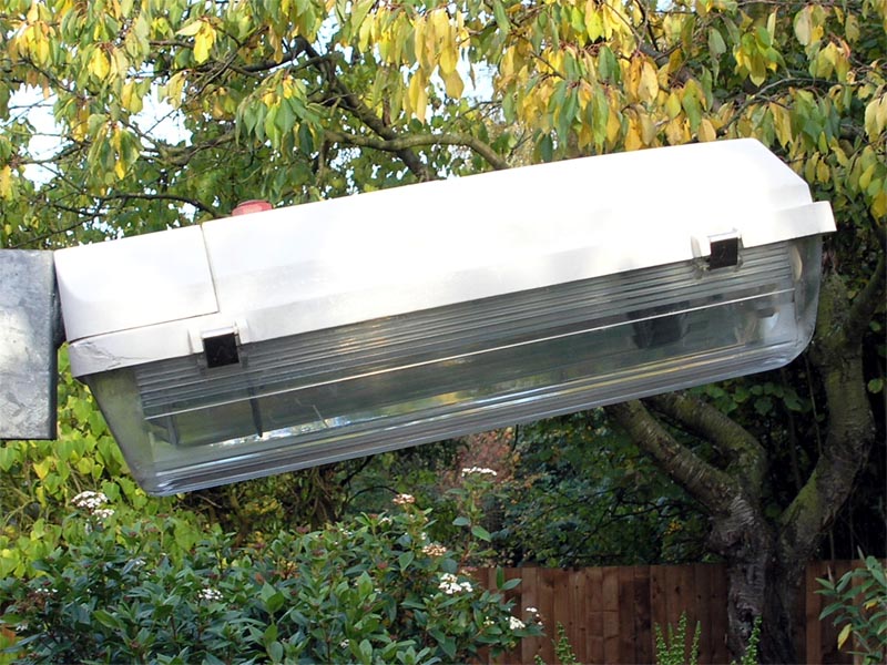
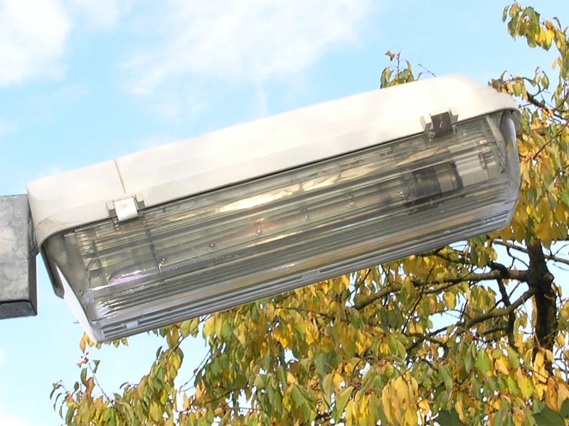
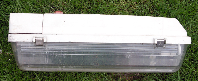
facing profile
The canopy of the lantern was made from formed glass reinforced plastic (GRP) formed into an angular, chunky
shape. This had a detachable rectangular cover at the back which could be removed so the "U" bolt to secure
the lantern could be seen; or an alternative side fixing could be fitted to provide post-top mounting. The bowl was curved - the same design as previous models.
|
|
|
|
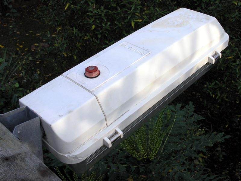
front profile
The lantern was in very good condition. Only some discolouration of the white plastic canopy and some slight rusting of the gear
showed that it had actually been in service at some point.
|
|
|
|
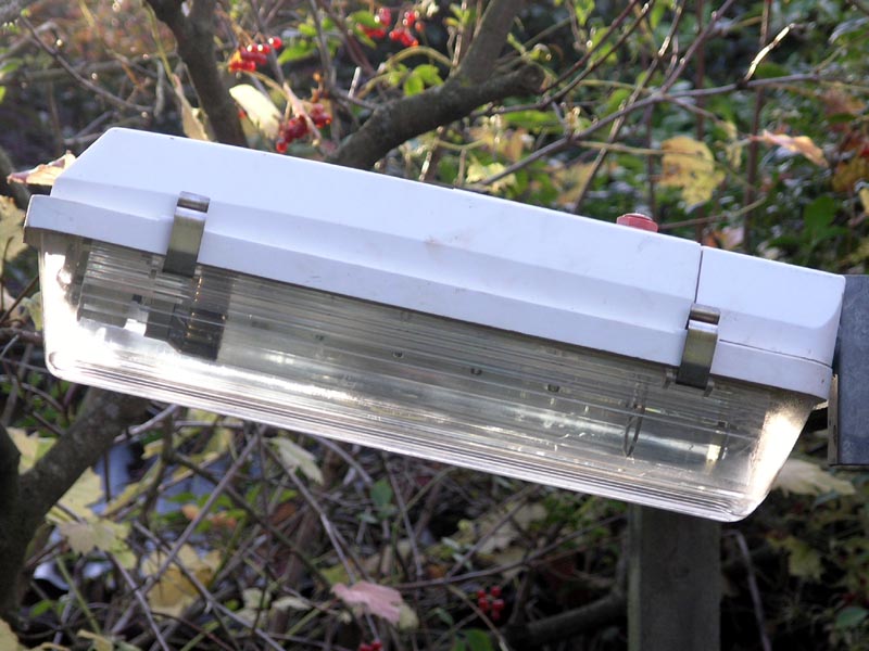
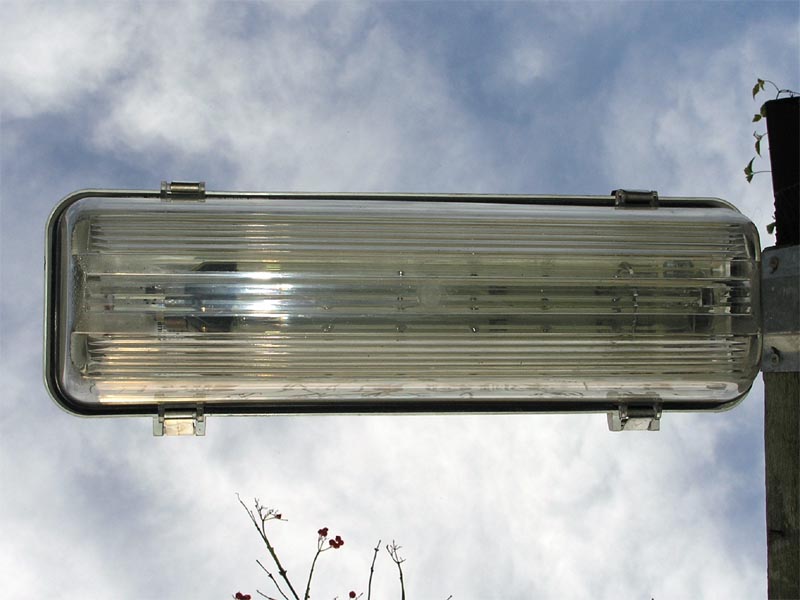
trailing profile
The design of the refractor can be appreciated in this shot. The upper parts of the refractor redirected the flux
from the lamp back down towards the street, adding to the main beams. The lower half the bowl was unimpeded allowing
as the flux emitted here was at the right angle for lighting the road. The base of the bowl included refractors
to spread the flux below the lantern, thus preventing the "bright spot" forming below.
This view clearly shows how the canopy profile matched the bowl profile, continuing the lines of the original metal
based lantern (the MI80). There were some design changes; the bulge for a top-entry option was removed and the
cover over the spigot mounting was removable.
This view also shows some limited damage to the GRP canopy. This was probably caused by the lantern being levered off
its original bracket.
|
|
|
|
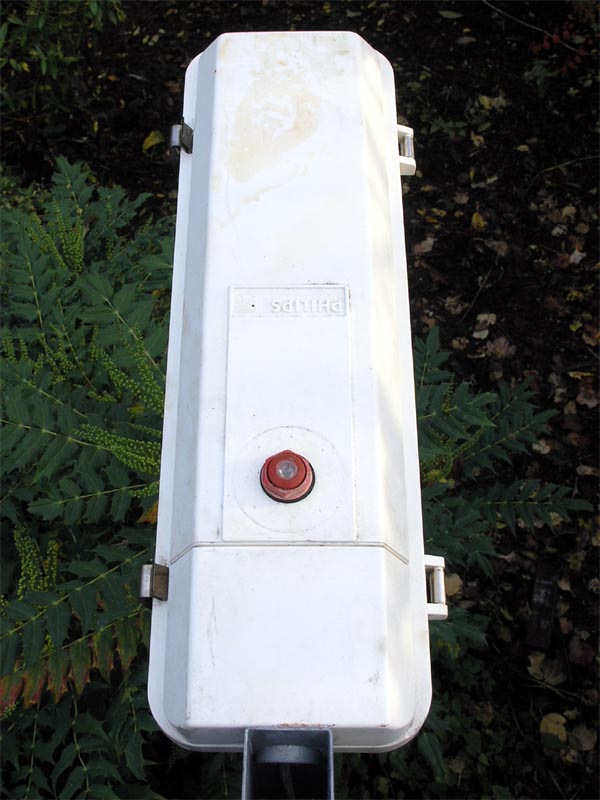
canopy
A small photocell was fitted. This was factory fitted and could be specified whilst ordering by adding "*1" to
the model name. (Interestingly the literature suggested a NEMA socket would be fitted but that's not the case
in this point.)
|
|
|
|
logo
Like most Philips lanterns, the top of the canopy featured the company's name and logo.
|
|
|
|
pedestrian view
The refractor prisms were moulded directly into the bowl; there wasn’t the idea of a section of
refractor plates which was common in earlier lanterns from the 1950s through to the 1960s.
|
|
|
|
vertical
The refractor pattern continued on the base of the bowl to spread the light beneath the lantern
in accordance with the strict BS 1788:1964.
|
|
|
|
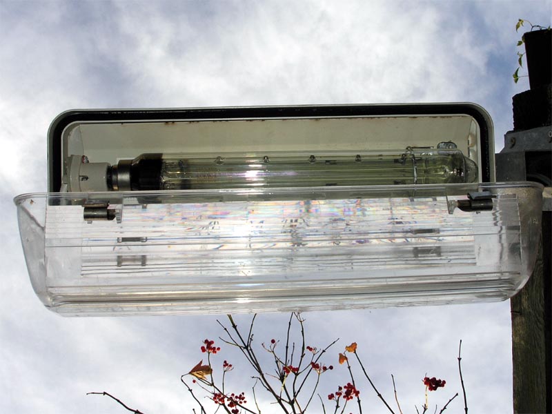
open bowl
The bowl swung open on its stainless steel clips and could be easily detached for cleaning (one of the better
and easier designs to deal with). (The smaller MI 36 had clips on either ends of the lantern rather than
on the side.)
The underside of the white-painted over-reflector can be seen.
|
|
|
|
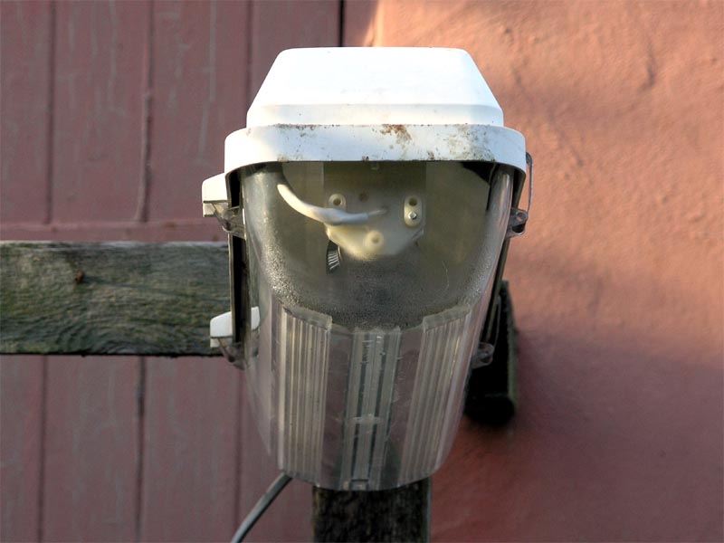
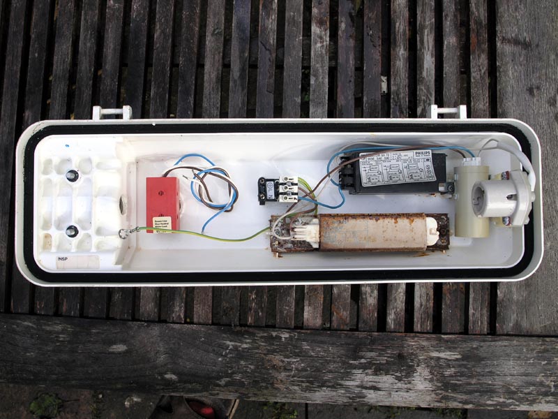
interior #1
Another major difference between the MI36 and earlier MI80 is found when the lantern is
taken apart. The gear is mounted in the canopy of the MI36 whilst it was mounted on the removable gear-tray
of the MI80. This seemed a strange decision as it would've made swapping the gear in this lantern more
difficult.
A sticker on the over-reflector included the lantern's model and lamp information:
MI 36 GO*1
9111 223 10200
SOX-E 36W & 55W SOX
240V 50Hz IP 65
The basic model number was "MI 36". The "GO" specified the gear-in-head option, whilst the "*1" specified
a NEMA socket for a photoelectric cell.
The gear was original to the lantern including a Philips 3351 ballast,
a Philips SX 72 ignitor and a Cambridge Capacitors
power correction capacitor with the date stamp of 1997.
I disconnected the wiring for the photo-cell.
All the components were mounted in the body of the canopy.
The almost universal spigot securing assembly of spigot housing along with two grub screws had also been changed.
It was replaced by an enclosed compartment (accessed by removing top of the canopy) which housed bolts and a U-shaped
spigot clamp.
|
philips mi 36: as aquired
The ever popular Philips MI 36 can be found all over the country, one of the major modern
SOX units to be found on our streets.
This model takes a 55W SOX.
The original location of the lantern is unknown, being found in the council's skip.
|