new
manufacturers
installations
collection
restorations
timeline
identification
publications
glossary
mailing list
site map
links
about
contact

amber lantern


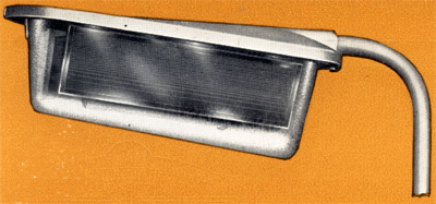
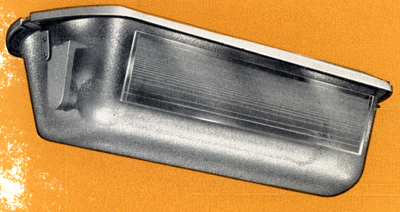
The Amber is an enclosed side entry lantern for use with type SO/H sodium vapour discharge tubes.

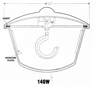
Whilst being essentially similar in design two units are available, these being for Group 'A' (85/140 watt) and 
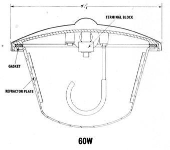
Group 'B' (45/60 watt) Roadway lighting.


Application
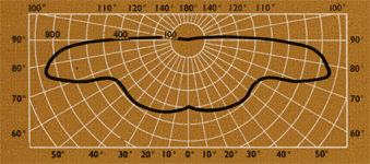
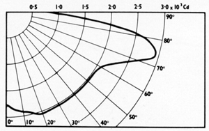
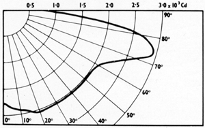
For Group 'A' and Group 'B' roads. The lanterns provide a non-cut-off medium angle beam distribution as defined in British Standards 1788 (revised).


Specification
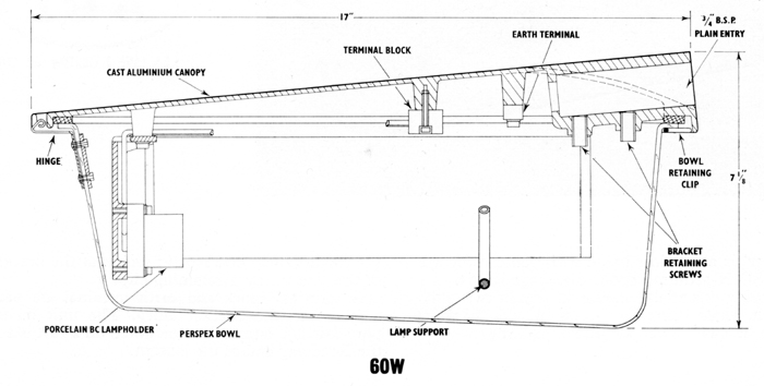
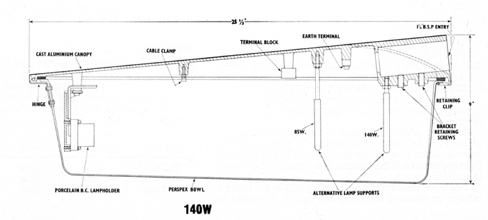
Both units have a cast aluminium canopy with an enclosing 'Perspex' bowl and confrom to the requirements of British Standard 1788 for street lighting lanterns.

The canopy is a single piece silicon aluminium alloying casting with interior painted white and exterior painted aluminium.

Refractor plates are sealed to the inside of the one piece 'Perspex' bowl which is slightly diffused to obscure a direct view of the interior and to aid the daylight appearance of the lantern. The exterior of the bowl is entirely smooth.

The bowl sits evenly on a gasket within the lantern canopy to ensure a weatherproof seal. It is hinged at the roadway end and is held secure at the bracket end of the lantern by a retaining clip.

A terminal block and earth terminal are provided adjacent to the bracket entry. The unit includes a porcelain BC lampholder mounted on a cast bracket at the Roadway end of the lantern.
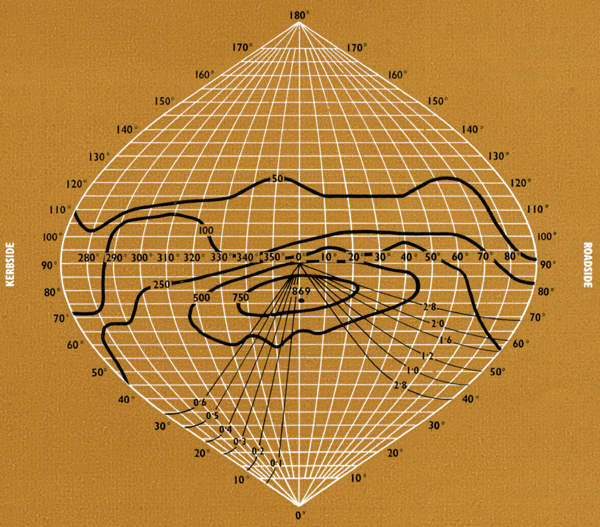
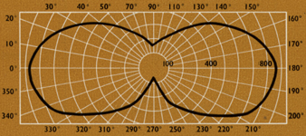

Light Distribution
Optical control is by means of a sealed in 'Perspex' refractor plates on the inside of the bowl, the remainder of the bowl being slightly diffused. Light distribution is in accordance with British Standards 1788 (revised).


Mounting
Both Group 'A' and Group 'B' versions are arranged for side entry mounting the Group 'A' version being suitable for 1¼" plain BSP 4" long and the Group 'B' version being suitable for ¾" plain BSP 3¼" long. To prevent corrosion th bracket retaining screws are inside the lantern.

Product No. Lamps Watts Entry Weight lbs Weight kgs
51/74010140Side104.5
51/7401185Side104.5
51/7900245/60Side2.4


The company reserve the right without notice to change the design or the specification of equipment included in this publication and supplied by them.


60W Amber Light Distributions


Light Output
(nominal average lamp lumens throughout life)
Lamp Watts
Lumens Rating

SO/H
60
4200
Total light output of lantern - lumens
Light output in lower hemisphere - lumens
Light output in upper hemisphere - lumens
Total light output ratio
Percentage of lantern in lower hemisphere
Percentage of lantern output in upper atmosphere
Direction Intensity Ratio (B.S. - CP 1004)
3445
3068
380
82%
89%
11%
2.19
Conversion Factors. Diagrams are drawn for average conditions of 60W SO/H lamp. For other conditions multiply by conversion factor.60W
Initial condition of lamp - clean lantern 1.18
Average condition of lamp - clean lantern 1.0

Light Distribtion data are only given for the guidance of the Lighting Engineer and represent the results of laboratory tests on a typical lantern taken from stock. The data are based on the lamp characteristics stated; if the latest lamp efficiency is different, the candela or lumen values should be calculated in direct propotion to the relative lamp lumens.


Polar curve of candlepower in a vertical plane through maximum intensity
Polar curve of candlepower over a cone through maximum intensity


Light Distribution Data
Lantern Specification
Semi Cut-Off AMBER (less gear) 51/74010
Side entry lantern
For one Mazda 140W (SO/H)
Sodium Discharge Lamp
1. Type

2. Downward light output
ratio
3. Lamp output - nominal
average lumens through life
4. Downward light output
clean lantern, average lamp
Semi-
cut-off (S)
0.78

12,220

9516

British Standard
1788 (Revised)
Suitable for A1, A2
road lighting
25-30 ft M.H.

See CP 1004 tables

Main Beam

Principle vertical polar curve
5. Peak intensity ratio
6. Angle of elevation
upper limit of beam
7. Angle of elevation
lower limit of beam
2.03
79o

70o

1.8-4

75o must be
within beam
Downard Zone
Up to 30o from vertical
8. Maxiumum intensity ratio
9. Minimum intensity ratio
7. Max intensity/peak intensity
1.34
1.18
0.66

not to exceed 1.7
not less than 0.3
not to exceed 0.7
Run Back

Polar curve in plane parallel to road
11. Angle of elevation at which
intensity ratio is 1.2
12. Intensity ratio at horizontal
82.5

0.35
between 80-86

not to exceed 0.7
Toe-In
13. Angle of azimuth between
beam centre and road axis
0o
not to exceed 15o