|
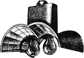
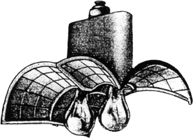
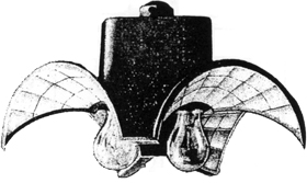
general construction
The reflectors consist of one piece castings glazed with silvered glass facets, cut from flat sheet,
embedded in a special atmospheric resisting cement. Each facet is set at the exact angle and is of a calculated
size to produce the desired light distribution.
Material: Cast iron or Aluminium non-corrosive alloy.
Finish: Green or Aluminium. Other colours to order.
Tapping: ¾" gas thread as standard. Tappings to 1¼" to order.
Lamp Holders: Bayonet Cap or Edison screw. Anti-vibration B.C. type as standard. Rigid Edision screw or rigid Bayonet Cap when specified.
approximate dimensions and weights
| Two Way |
12 |
15½ |
11½ |
12 |
10½ |
9½ |
19 |
8 |
19 |
8 |
| Three Way |
13 |
15 |
11 |
11½ |
9 |
9½ |
19½ |
9 |
17½ |
7½ |
| Four Way |
17 |
20 |
11 |
16 |
11½ |
9½ |
23½ |
11 |
21 |
9 |
technical description
The reflectors are designed to produce a light distribution of the required characteristics
to ensure good uniformity of illumination and road brightness. The peak candle power is projected at an angle of 10o below the horizontal.
The recommended average economical spacing of posts is ten times the mounting height of the lamp filament.
Type of lamp. B.S.I. type clear gas filled singled coil tungsten filament lamps for standard use. Where the reflectors are
installed under aderse circumstances as regards mounting height etc., pearl lamps may be used as explained
later. Also, where coiled coil lamps are employed, these should always be of the pearl type unless the mounting height is more than 17'.
The particular advantages of the Twin Lamp construction are:
- Additional safety against lamp failures. If one lamp fails the light from the remaining lamp will be sufficient until the faulty lamp has been replaced.
- Under certain circumstances the lamps may be connected to different supply circuits thus reducing the risk of complete failure due to a local supply fault.
- The lamps may be connected so that one lamp is disconnected at midnight or other desired time. The remaining lamp need not be the same wattage as
the first lamp as the lamp position can be pre-set, at a slight additional charge, in accordance with the light centre length of the lamp.
mounting height
The table below gives the suggested mounting heights for various wattages. Where the mounting height is less
than these values, it is advisable to either use pearl lamps or one of the numerous grades of semi-diffusing
silvered glass instead of the clear mirror glass. Reflectors glazed with different grades of this glass may be
loaned for trial purposes and the grade best suited to the conditions can then be chosen.
| Recommended minium Height to Light centre. |
15' |
15' |
16' |
17-20' |
20-25' |
23' and over |
angular settings
The table overleaf indicates the present range of angular settings, but we make a regular practice of designing special patterns whenever
we find unusual positions.
The angles are read in a clockwise direction looking down on the fitting. It must be remembered that the angle of the reflector
does not follow the angle of the road. For instance, in the case of a straight road with side of road mounting, 180o reflector
is not required, the correct one being usually 165o or 170o. (i.e. ensuring that a minimum of light is wasted on
the boundaries of the road.) Another example is an exact 90o sharp bend; here either a 100o or an 80o
fitting will be necessary according to whether the post is on the inside or outside of the bend. The general lines of procedure are
described in the introductory matter of our general catalogue.
It will be seen that two types of reflectors employing two lamps are tabulated under the Group "A" size, the Two Light and the Twin Lamp. In the
case of the Two Light the lamps are normally arranged in line with the length of the road and with the Twin Lamp they are arranged transversely.
technical service
The personal services of our technical staff at the works are at our clients' disposal at all times.
They are prepared to visit a district in order to advise on all street lighting problems, also to inspect
every individual lighting position to ascertain the correct reflector, or this latter work can be done reasonably well from plans.
They are also ready to carry out photometric tests on site, for which purpose they are equipped with the latest portable photometers available.
schedule of angles
180o
165o
155o
140o
130o
|
180o
|
165o
|
195o 82½o 82½o
190o 85o 85o
180o 55o 125o
155o 90o 115o
150o 120o 90o
150o 140o 70o
130o 130o 100o
120o 120o 120o
|
180o 90o 90o
195o 82½o 82½o
165o 105o 90o
165o 90o 105o
|
|
110o 90o 70o 90o
90o 90o 90o 90o
|
110o 90o 70o 90o
|
|
|