
1. The OSIRA High Pressure Mercury Vapour Electric Discharge Lamp
Since its original introduction the OSIRA lamp and its equipment have been improved in many respects and the
present lamp and choke coil give the following advantages:
- Reliable striking on all supplies of 200 volts and over.
- Good uniformity in lamp characteristics.
- Improved ability to withstand large surges in supply voltage.
- Reduction in time to relight after extinction.
- Reliable life and lumen maintenance.
- Improved mechanical construction eliminating transit breakages.
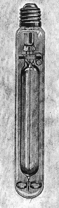 |
The "OSIRA" Lamp
For dimensions and
prices see page 9.
|
The lamp is tubular and is fitted with a G.E.S. cap. The actual source of light is a luminous cord of gas about
¼in. diameter which stretches out between the two electrodes. The lamp must be burnt in a vertical position with
the cap up. OSIRA lamps can be supplied for burning vertically with the cap down if specially ordered for this
purpose.
The lamp must not be exposed to driving rain, which is liable to crack the outer bulb. Water-drip will have the same effect,
and it is essential to see that lanterns are weatherproof and that the joints between lanterns and brackets are pefectly watertight.
The use of the box described on page 22 is strongly advised.
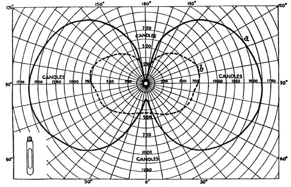
Polar curves showing light distribution in vertical plane from (a) 400-watt
OSIRA lamp and (b)
500-watt tungsten filament lamp. |
2. Supply System
The lamp is suitable for A>C. only and not for D.C.
3. Range of OSIRA Lamps.
The OSIRA lamp is at present (July, 1935) made in two wattages and four voltage ranges as follows:-
| 200/210-volt 250-watt and 220-volt 250-watt | These two lamps must be used with the G.E.C. Z 1860 L50 Choke. |
| 230-volt 250-watt and 240/250-volt 250-watt | These two lamps must be used with the G.E.C. Z 1860 H50 Choke. |
| 200/210-volt 400-watt and 220-volt 400-watt | These two lamps must be used with the G.E.C. Z 1870 L50 Choke. |
| 230-volt 400-watt and 240/250-volt 400-watt | These two lamps must be used with the G.E.C. Z 1870 H50 Choke. |
4. Voltage of supply.
The voltage rating of OSIRA lamps shuold be chosen to suit the actual voltages available during buring hours at the units rather
thant the nominal voltage of the supply, and the table below shows the range of mains voltages which the lamps cover satisfactorily.
When the lamp is first switched on the gap between the special starting electrodes is subjected to the full voltage of the supply
mains there is not voltage drop in the choke until current commences to flow). A discharge immediately takes place in the rare
gas filling and starts the main discharge.
The minimum voltage at which the OSIRA lamp will start up is independent of the choke tappings in use, and under normal conditions
the G.E.C. lanterns is as given below, although in exceptionally cold wather these minima may be 5 volts higher :-
| Range of voltages available at units of the installation during burning hours | Recommended votlage rating of OSIRA lamp | Minimum starting voltage |
| 190 to 220 | 200/210-volt lamp | 185 |
| 210 to 230 | 220-volt lamp | 200 |
| 220 to 240 | 230-volt lamp | 210 |
| 230 to 260 | 240/250-volt lamp | 215 |
5. Choke Coils.
The characteristics of the OSIRA lamp alone are similar to those of an arc. That is to say, the lamp when burning corresponds to
a "negative" resistance, and unless an impedance is used in series with it to stabilise the discharge the current will rise until the
lamp bursts.
If a resistance is ued, a large wattage loss is inevitable, but on A.C. supplies a choke may be used and the wattage losses reduced
by careful design to a very low figure. The G.E.C. chokes are so designed, and must always be used in conjunction with the OSIRA
lamp. They are further arranged to reduce to a minimum the effect on the lamp wattage of voltage variations or difference in
individual lamp characteristics.
The chokes are provided with tappings so that when the correct tappings are used the lamp watts will be maintained at, or about,
the rated value.
It is most important that the correct voltage lamp and choke tapping should be used. Each choke is provided with a metal instruction
plate giving the method of selecting the appropriate tappings.
The tappings used should correspond to the average actual maisn voltge to be expected at the unit during burning hours and the
voltage drop in the cables (for example, in a long length of street lighting) should be taken into account when deciding which
tapping to use at each unit, working to the nearest five volts.
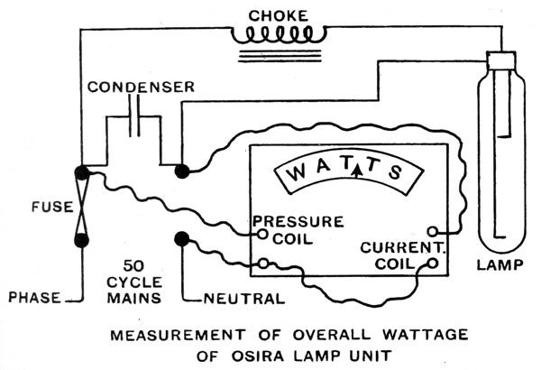
In special cases where an accurate check on the performance of the unit is required the overall wattage should be measured by
an A.C. wattmeter connected as shown in the diagram. Measurements by special ammeters and/or voltmeters are valueless.
6. Frequency.
The standard G.E.C. chokes and condensers are designed to suit a supply of exactly 50 cycles frequency.
Special chokes and condensers to suit other frequencies can be supplied on application.
If the lamp is used on supplies whose frequency is 25 cycles or less, the flicker effect may
become objectionable, though for outdoro use a 25-cycle flicker is not noticeable under normal street lighting
conditions.
7. Power Factor And Condensers.
The power factor of the lamp and choke (without condenser) is not unity for two reasons :-
- (a) In the first place, the lamp current is not strictly sinusoidal, and, therefore, even if the lamp
voltage and lamp current should pass through zero at the same time the volt-amps. will be higher than the
wattage. The ratio being about 1.08 to 1 represents a power factor of about 0.92 which can neither be said
to be lagging or leading.
- (b) The addition of the G.E.C. choke coils causes a lagging power factor, which, together with the value
of 0.92 referred to above, gives a power factor for the lamp and choke combined of about 0.6 lagging.
The use of G.E.C. condensers raises the power factor of the complete unit to between 0.80 and 0.90, reducing the
wattless current in the mains. The limit of correction is the figure of 0.92 given under (a) above.
The values of current and power factor for different lamps and voltages are shown tabulated on page 30.
8. Fuses.
Fuses for each unit are recommended, especially in the case of street lighting installations, to protect the wiring at
the individual units.
Fuses of 10 and 15-amp capacity are suggested for the 250 and 400-watt units respectively to take care of the condenser
charging current when first switched on.
9. Cables.
Cables should be of sufficient size to take the starting current of the unit, which is about double the running current.
10. Running Characteristics of Complete Unit.
The overall efficiency of the unit will vary according to the type of choke used. With the G.E.C. chokes the overall
consumption will be increased by only about 5 per cent. on the nominal lamp watts. The average values of current, and power
factor, both with and without condensers in use, are shown tabulted on page 30.
11. Voltage Variations.
When a lamp is alight, voltage variations above and below normal will naturally affect the wattage and light output, and when using
the special G.E.C. chokes described a 1 per cent. rise in mains voltage will give approximately a 2.6 per cent. rise in lamp watts
and 3.5 per cent. rise in lumen output (and ilumination.) This compares favourably with the characteristics of a filament lamp.
An interruption in the supply, even though only momentary, may cause the lamp to extinguish, and a rapid voltage drop may have
the same effect. If the reduction in volts takes places slowly (not more than 10 or 15 per minute) the lamp will stand a reduction
of 40 or 50 volts, but a sudden drop of over 25 volts may cause the lamps to go out.
The lamp is more susceptible to this effect if it is running at less than 400 watts, either owing to low mains voltage or incorrect
choke tappings being in use.
Small voltage variations above and below the average are not so serious in their effect on the life of OSIRA lamps as on that
of filament lamps.
If a 230-volt filament lamp is run for one hour at 240 volts and one hour at 220 volts it will suffer deterioration during
the one hour of over-volting, which will not be compensated for by the one hour of under-volting.
An OSIRA lamp treated similarly will have the same life as if the average voltage of 230 had obtained for the two hours.
The life and lumen maintenance of the OSIRA lamp will, of course, be reduced if the average voltage is maintained
above 400, and a prolonged rise of 20 volts, corresponding to a rise of about 85 to 90 lamp watts, will cause overheating of the
inner bulb.
12. Switching.
If the supply to the lamp is switched off the lamp must cool down before it will relight. This will take place automatically
(if the switch is left on) after about seven minutes or so, depending on the surrounding temperature.
On account of the starting current taken it is recommended that switchgear suitable for 1,000-watt tungsten filament lamps
should be used with the 400-watt OSIRA lamp and that sutiable for 500-watt tungsten filament lamps with the 250-watt OSIRA
lamp. The makers of the switchgear should invariably be consulted.
If the lamp is switched on for tests it should be allowed to burn up to full brilliance before switching off again, as
otherwise the electrode fillings may be adversely affected.
13. Starting Conditions.
When the switch is first "made" the lamp receives the full voltage of the mains across the electrodes (regardless
of the choke tappings in use), but as soon as the discharge commences in the rare gas filling a fairly heavy current flows,
resulting in a sharp drop in the voltage across the electrodes.
There is an initial switching surge, similar to that experienced with filament lamps, which may last for a few cycles and vary
in value according to the switching conditions. The period is far too short to show on the diagram of "Starting Characteristics."
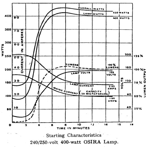
Immediately after this the lamp takes the "starting current" which is about double the running current, as shown in the diagrams
on page 27, where, for a 400-watt lamp, the mains current for the first minute or two is about 3½ amps. at a
power factor of only about 0.15, giving an overall consumption of 150 watts. After a few minutes the lamp settles down to
steady running as shown in the diagram.
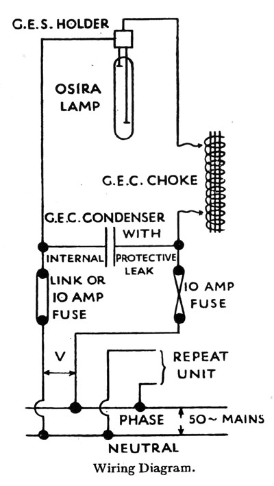
14. Wiring.
The lamps are arranged for parallel burning, each lamp having a choke in series with it, preferably on the phase side. The condenser,
if required for power factor correction, is connected across the mains on the mains side of the choke. The maximum benefit in the
reduction of wattless current in the mains will be obtained with the condenser as near the unit as possible. The wiring diagram shows
the arrangement.
The G.E.C. chokes are protected against damp by vacuum bitumen impregnation and have no exposed live terminals, but they should not
be exposed to direct water splash or drip.
The choke tappings must be chosen in accordance with the metal instruction plate fixed to the choke, and it is of interest to
take a practical example of a street lighting circuit on a declared voltage of 230 volts 50 cycles supplied from a feeder at one
end. Consider seven 400-watt OSIRA lamps supplied as shown below and assume the following :-
Cable 7/0.44 spacing 150 and average voltage at sub-station during burning hours 230 volts. If the cable feeds these lamps only
(that is to say, it is not affected by any load, such as domestic consumers) the usual calculations give us, under burning conditions,
the figures shown, assuming a drop of 2 volts in the main feeder.
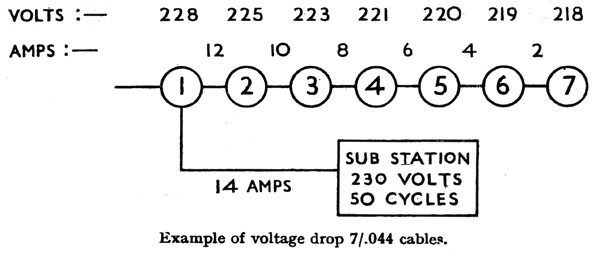
Although the nominal voltage of the supply is 230, we see that the post voltages range from 228 to 218 volts, and from the
preceeding paragraphs 3 and 4 we note that the correct lamp and choke are the 220-volt lamp and the Z 1870 L 50 choke. This because
the 230-volt lamp is suitable for post voltages of 220 to 240 and the 220-volt lamp for post voltages of 210 to 230.
The G.E.C. choke Z 1870 L 50 will therefore be used at each unit, using the nearest tapping to suit each post. We shall therefore
have :-
|
| 1 | 228 | 230 |
| 2 | 225 | 225 |
| 3 | 223 | 225 |
| 4 | 221 | 220 |
| 5 | 220 | 220 |
| 6 | 219 | 220 |
| 7 | 218 | 220 |
It will be noted that the choke setting is always within 2 volts of the actual value. The G.E.C. chokes are specially designed
so that this results in a lamp wattage within a few watss of the rated value - apart, of course, from any changes due
to subsequent variation in the sub-station voltage.
It is recommended that the selected tappings should be connected to the incoming and outgoing wiring, taped over,
and coated with shellac or similar preparation so that the unit is free from exposed live parts. The remaining tappings
can be tucked out of the way, the ends being insulated.
An earthing screw is provided on the G.E.C. chokes and condensers. If bare conductors are used for earthing these
components, the bare wire must be kept clear of the choke windings.
15. Supplies other than 200/250 volts 50 cycles.
100/130 volts 50 cycles
For these supplies a small step-up transformer will be needed for each unit, or a larger transformer for a group
of units. Particulars on application to G.E.C. (Z Department).
Supplies at 40 cycles, 60 cycles etc.
The standard G.E.C. chokes are accurately adjusted to suit supplies at 50 cycles. For any other frequency specially
adjusted G.E.C. chokes are necessary. Particulars on application to G.E.C. (Z Department).
16. Characteristics.
The following table shows the approximate values of main current and power factor for units on 50-cycle supplies
ranging from 200 to 250 volts :-
|
|
|
| 200/210 volt 250 watt | 200 | 4¼ | 2.3 | 0.55 to 0.6 | 3½ | 1.6 | 0.8 to 0.85 |
| 210 | 4 | 2.3 | 3 | 1.6 |
| 220 volt 250 watt | 220 | 3¾ | 2.1 | 2¾ | 1.4 |
| 230 volt 250 watt | 230 | 4½ | 2.0 | 0.55 to 0.6 | 3½ | 1.3 | About 0.9 |
| 240/250 volt 250 watt | 240 | 4½ | 1.9 | 3¼ | 1.2 |
| 250 | 4 | 1.9 | 3 | 1.2 |
| 200/210 volt 400 watt | 200 | 5½ | 3.6 | 0.55 to 0.6 | 4¼ | 2.6 | About 0.8 |
| 210 | 5¼ | 3.6 | 4 | 2.5 |
| 220 volt 400 watt | 220 | 5 | 3.5 | 3¾ | 2.4 |
| 230 volt 400 watt | 230 | 5½ | 3.2 | 0.55 to 0.6 | 4 | 2.2 | 0.85 to 0.9 |
| 240/250 volt 400 watt | 240 | 5 | 2.9 | 3¾ | 2.0 |
| 250 | 4¾ | 2.9 | 3¼ | 1.9 |
17. Photometric Tests.
Photometry is difficult and complicated, and extremely variable results will be obtained unless special
instrumentals and trained observers are employed. The wattage of the unit should be checked as described
in paragraph 5.

|