new
manufacturers
installations
collection
restorations
timeline
identification
publications
glossary
mailing list
site map
links
about
contact

Clearmain 8401 Lantern
For Osram Mercury Lamps

Specification Clearmain 8401

Use
Main road lighting, especially roads in the vicinity of airfields. The lantern has a medium angle beam distribution. Peak intensity occurs at 75 degrees, and at 80 degrees it is two-thirds of the maximum value. The cut-off type of construction produces a rapid run back over 80 degrees falling to a negligible figure at the horizontal. The lantern falls within the specification issued by the Ministry Of Transport, whcih is reproduced on the back page. 
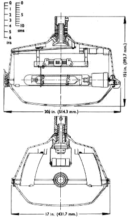
Lanterns should be mounted at a height of 25 ft. and spaced not more than 120-130 ft. apart. Suitable for road widths up to 50 ft.


Lamp
For use with a 250W or 400W Osram MA/V lamp.


Mounting
Top entry, standard tapping 1.1/4 in. B.S.P. The lantern can be provided with a device to give levelling in any plane to a maximum of 5 degrees from the horizontal when required with the M.O.T. specification overleaf.


Lantern Body
Totally enclosed die-cat aluminium-silicon alloy. The body carries the terminal block, wiring, magnetic deflector, lampholder, lamp steady and the reflectors which make up the optikon.


Lampholder
Porcelain G.E.S. wired with heat-resisting insulated wire to a porcelain terminal block.


Over-Reflector
Immediately above the lamp is a non-magnetic reflector. The reflector plate serves the dual purpose of reflecting light and preventing rising hot air from overheating the magnetic deflector.


Magnetic Deflector
The magnetic deflector enables an MA/V lamp burning horizontally to operate as efficiently as it does in its normal perpendicular position. The deflector is mounted on the reflector plate. It is connected in series with the lamp and consumes 1 watt. The magnetic deflector can be used with either the 250W or 400W lamp, conversion from one wattage to the other being made by changing a connection.


Optical System
Two curved glass mirrors are held inside the body to provide the light control. All mirrors are first quality and are coppered, lead backed and secured by clips. A die-cast light alloy frame, hinged to the body and secured by a stainless steel toggle catch, supports a pressed heat-resisting glass dish.


Weathering Finish
The alloy used is especially selected for its resistance to corrosion and is processed to give a pleasing appearance.


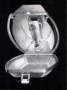
The lantern opened to show optical system, lamp mounting and over-reflector carrying the magnetic deflector


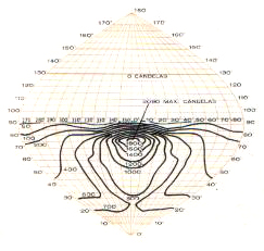
The iso-candela diagrams are based on an average lamp light output through life from a 250W Osram MA/V lamp (8,750 lumens average).


250W400W
Directional intensity ratio3.12.6
Light above horizontal2%2%
Light output ratio56%55% apprx
Lumens in the lower hemisphere    3810    7080


Light distribution data are given for the guidance of the lighting engineer and represent the average results of laboratory tests on a number of lanterns taken at random from stock. The data are based on the lamp characteristics stated; if the latest lamp efficiency is different, the candela or lumen values should be calculated in direct proportion to the relative lamp lumens.


Lantern weight: 28lb (12.7 kg).


Ministry Of Transport Specification For Street Lighting Lanterns To Be Used In The Vicinity Of Airfields

(1) Foreward
A number of Government Departments concerned with flying have powers under the Air Navigation Acts by which they can require the restriction of lighting in the vicinity of airfields which may be a danger to air navigation. In so far as street lighting in concerned, the requirements have in the past been met by the use of cut-off type lanterns, which emit a negligible amount of light above the horizontal. For such lanterns the British Standard Code Of Practice (C.P. 1004: Part 1, 1952) recommends spacings of 90-100 ft. instead of the 120-150 ft. usual for non-cut-off lanterns. This specification has been prepared following practical tests to determine requirements, and defines the characteristics of lanterns which can be employed in the vicinity of airfields where a limited amount of light showing above the horizontal is permissible, and which at the same time can provide satisfactory street lighting at spacings commonly employed for medium angle beam lanterns.


(2) General
The general requirements for construction shall be those laid down in B.S. 1788:1951, "Street Lighting Lanterns", in so far as they apply. Details of the lantern shall be provided by the manufacturer and shall include a scale drawing of the lantern, an iso-candela diagram of its light distribution, a statement of the light output ratio and instructions for adjustment of the lantern at the time of erection. Lanterns may be of the open or enclosed type. Side or top entry may be adopted. The means of supporting the lamp shall be so designed and constructed that the position of the lamp in the lantern relative to the optical equipment remains substantially the same throughout the life of the lantern. If the supports are adjustable a suitable method of locking them shall be provided. The provisions of this specification shall apply whatever type of light source is used in the lantern.


(3) Light Distribution Above The Horizontal
The intensity at and above the horizontal in any vertical plane through the centre of the lantern shall not exceed, when the lantern has been erected and adjusted in accordance with the manufacturer's instructions, the values quoted in the table below.

Angle from the downward vertical90°92°94°96°100°110°120°130°140°150° and above
Maximum permissible intensity (Candelas)750300957560403020100


(4) Light Distribution Of Group A Lanterns Below The Horizontal
The light distribution at angles below the horizontal shall be of the normal medium angle beam type. For Group A lanterns, the maximum intensity shall not be less than 2,000 candelas, and shall occur at 75° from the downward vertical with a tolerance of +/- 2° when the lantern has been erected and adjusted.


(5) Adjustment Of Lanterns
Means of adjustment of the lantern after erection shall be provided together with a device to indicate the angular setting. The indicating device shall be accurate to +/- ½°