|
Specification Clearmain 8430CM
Use
Main road lighting; the lantern is designed for mounting at 25 ft. (7.62 m) and spacing at
120 ft (36.58 m) optimum, but can be used up to 150 ft. (45.72 m) maximum; road
width up to 30-40 ft (9.14 - 12.19 m).
Lamp
250W or 400W Osram colour corrected mercury type MBF/U lamp.
Mounting
Z8430CM. Side entry. The lantern requires not less than 4 in. of horizontal unthreaded 1.1/4 in.
B.S.P. When fully home two 7/16 in. dia. Allen type grub screws grip the barrel.
Lantern Body
Die-cast aluminium alloy. The body carries the reflectors, lampholder, terminal block and
heat resisting insulated wiring. An earthing screw and porcelain cable cleat are provided.
Lampholder
Porcelain G.E.S. wired with heat-resisting insulated wire to the porcelain terminal block.
Optical System
The pressed prismatic refractor bowl (Z6631) is made of heat-resisting glass. The refractor
is secured in a die-cast light alloy ring which is supported on the main body casting by a
hinge and quick released stainless steel toggle catch. The toggle has a safety catch so
that two distinct actions are needed before the refractor swings free. The first action releases
the toggle catch and lowers the hinged ring and refractor to a safety position, where it is
still held at each end. The toggle catch, which is at the bracket end, can then be
unhooked allowing the refractor to swing down, giving access to the lantern interior. A
gasket is fitted in the lower rim of the lantern body and when the lantern is closed this
makes a weatherproof joint with the hinged ring supporting the bowl.
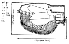
In use the lamp is moutned with its axis tilted down 5° from the horizontal and the
plane of the rim of the bowl at about 15° to the horizontal. By arranging for the
lampholder to be outside the bowl and the lamp to enter at an angle (patent applied for)
a compact lantern of small size is possible. The slight upward inclination of the
lantern towards the roadway in use directs maximum amount of light at night on the
carriageway and adjacent area (verge, footwalk, side-turning, etc.) on both sides,
and gives a very pleasing appearance to the lighting units by day. A good light output
ratio (70%-76%) is obtained.
Weathering Finish
The alloy used is especially selected for its resistance to corrosion. Further protection
is obtained by the use of a special one-coat aluminium finish stove enamel.
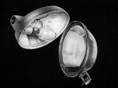 |
| The Z8430CM lantern with the refractor bowl lowered showing the lamp, reflectors and
general construction. |
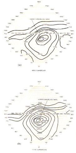
The iso-candela diagrams are based on an average lamp light output through life from:
(a) 250W Osram mercury type MBF/U lamp (9,250 lumens average).
(b) 400W Osram mercury type MBF/U lamp (16,800 lumens average).
| 250W | 400W |
| Directional intensity ratio | 3.3:1 | 2.5:1 |
| Light above horizontal | 20% | 20% |
| Light output ratio | 75% | 70% |
| Lumens in the lower hemisphere | 5,600 | 9,400 |
Light distribution data are given for the guidance of the lighting engineer and represent the
average results of laboratory tests on a number of lanterns taken at random from stock.
The data are based on the lamp characteristics stated; if the latest lamp efficiency is different,
the candela or lumen values should be calculated in direct proportion to the relative lamp
lumens.
Lantern weight: 18lb (8.16 kg).
|
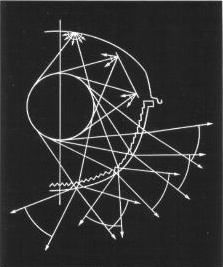 The main optical system consists of three separate sets of refracting prisms on the
inside of the heat resisting glass bowl, the outer surface being completely smooth
to avoid ledges and crevices where dirt can accumulate, and to facilitate cleaning. The
horizontal set of prisms on the side of the bowl concentrate the sideways emitted light
outwards towards the further parts of the street, and the vertical prisms on the end
portions of the bowl also concentrate the wide angle light laterally towards the same
area; horizontal cross-refracting prisms on the bottom of the bowl spread the downward
emitted light outwards to provide lower intensities nearer the lantern with
increasing value at wider angles up to the direction of maximum intensity.
The main optical system consists of three separate sets of refracting prisms on the
inside of the heat resisting glass bowl, the outer surface being completely smooth
to avoid ledges and crevices where dirt can accumulate, and to facilitate cleaning. The
horizontal set of prisms on the side of the bowl concentrate the sideways emitted light
outwards towards the further parts of the street, and the vertical prisms on the end
portions of the bowl also concentrate the wide angle light laterally towards the same
area; horizontal cross-refracting prisms on the bottom of the bowl spread the downward
emitted light outwards to provide lower intensities nearer the lantern with
increasing value at wider angles up to the direction of maximum intensity.