Specification
Clearspace
USE
There are certain essential requirements for the equipment used for the lighting of Outdoor Sub-Stations.
1. The lanterns must not require tall poles to support them. Such poles cannot be used in many positions because they would be
dangerously near to live overhead conductors.
2. The lantern's light distribution must not produce glare in the eyes of a Maintenance Engineer standing on the ground.
3. The distribution must be designed to give good illumination of the underside and vertical surfaces of conductors, insultators,
switches and other equipment mounted above eye level.
4. The distribution must give even illumination on a horizontal plane and so prevent the formation of shadows and dark pockets.
5. The lantern must be mounted so that it is accessible for relamping without the use of ladders.
6. The equipment must be designed so that initial charges and maintenance costs are low. It must be resistant to atmospheric
corrosion.
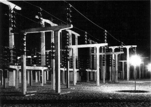
The lantern described here has been designed to meet the above requirements and has been approved by the C.E.G.B. for use in their
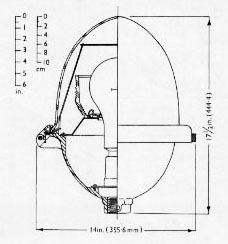
Sub-Stations. It is intended for mounting at a height of 8-10 ft. above ground. A special 8 ft. pivoted steel column has been designed
for use with the lantern so that it can be maintained by a man standing on the ground.
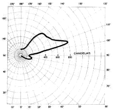
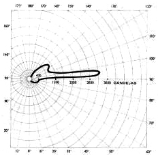
The precise positions of lanterns in a particular Sub-Station depend on the layout of the apparatus which needs to be seen most
clearly, such as overhead switches and insulators. The lantern is designed to project a concentration of light at angles of
10° to 20° above the horizontal where it is most needed, and to restrict intensities at and below the horizontal.
|
LAMP AND LAMPHOLDER
300W Tungsten filament, Osram General Service.
G.E.S. porcelain lampholder.
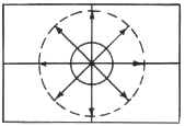
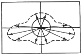
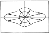
OPTICAL SYSTEM
Control of the light distribution is obtained by the use of a prismatic glass refractor. Three types
of refractor are available: symmetric distribution; non-axial distribution and axial asymmetric. The
choice of refractor depends upon the relative positions, as seen in plan, of the lantern and
the apparatus requiring most illumination. A diagrammatic explanation of the three forms of optical
system is given on page 4.
MOUNTING
The entry at the bottom of the lantern is tapped 1½in. B.S.P.; a grub screw is fitted for
locking the lantern on to the support.
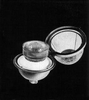
CONSTRUCTION
The lantern body is of non-ferrous cast alloy, specially selected for its resistance to
corrosion. It has a cast alloy hinged ring holding the glass globe which can be swung open to give
access to the interior. These alloy castings are Pyluminised and finished stove enamelled aluminium
colour. The lantern is totally enclosed and dust proof, a neoprene gasket being provided on the
lip of the glass globe. The hinge pin, screw fastener and screws exposed to the weather are of
stainless steel.
An aluminium heat baffle is provided above the lamp to prevent excessive heating of the special
glass globe. The refractor is supported on a white vitreous enamelled plate and held in position
with spring clips.
A double-headed arrow on the outside of the lantern indicates the direction of the main beams of
light, and both the refractor and refractor plate can be fixed in only one direction.
Export Packing details on application
|