|
holophane refractors for street lighting
Purpose of Holophane Refractors
Holophane Refractors are made of transparent glass with prismatic surfaces mathematically designed to fulfil the following functions :-
- To intercept the upwardly-emitted light of the lamp and redirect it downwards, so that it shall usefully serve for lighting the street.
- To distribute the light emitted downwards in such a manner as to produce approximately uniform illumination over a much larger area
than is the case when a bare lamp is used alone, or with any other equipment; and
- To diffuse the light so as to reduce the intense brilliancy of the bare filament and produce a pleasing appearance.
Construction of the Holophane Refractor
The Holophane Refractor consists of two pieces of pressed crystal glass one of which fits snugly within the other and is then clamped together
so as to form a single unit. The inside surface of the inner piece and the outer surface of the outer piece are smooth, making cleaning
easy. The outside surface of the inner pice and the inside surface of the outer have prisms so designed as to bend downwards the light
emitted upwards and also to bend upward the excess in light emitted downward near the vertical, thus greatly increasing the light given at
angles from 60° to 85° with the vertical and greatly extending the radius of effective illumination. Prisms are also arranged
to diffuse the light and thus reduce the intrinsic brilliancy of the unshielded filament.
Types of Holophane Refractors
There are three main types of Holophane Refractors, namely :-
- The Bowl Type.
- The Band Type.
- The Dome Type.
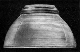
The Bowl Type Refractor is almost closed at the bottom the inner member having refractor prisms
covering its whole surface. This type therefore controls the entire light output of the lamp.
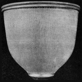
Holophane Bowl Type Refractor
Bowl Refractors are made in four different types of light distribution :
- Symmetrical.
- 2-Way non axial (160°)
- 2-Way axial (180°)
- 4-Way (90°)
The Band Type refractor, as the name implies, is made in the form of a band or cylinder. The opening below the
lamp permits a larger part of the light to pass directly down to the street surface beneath the lamp, and hence it is more suitable
for units which are closely spaced at a ratio of not more than 5 to 1, the distance apart to height, and for positions
where it is necessary to have a greater relative illumination in the vicinity of the unit.
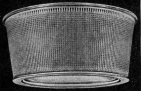
Holophane Band Type Refractor
The Dome Type refractor is a special design for use inside lighting diffusing globes. Since it is used inside
such globes, the outer member is replaced by another member having a further series of refracting prisms. The refractor has
therefore, horizontal refracting prisms on both the inner and outer piece.
Holophane Dome Type Refractor
Varieties of Bowl Refractors
Due to a notable advance in the design of Holophane Bowl Type Refractors for Street Lighting service, it is necessary to
give in some detail an explanation of their performance so that the different varieties may be used to the best advantage
in obtaining the most economical results under the varying conditions met with.
The Standard Bowl Type Refractor, as also the Band Type, is designed to bend the light by transmission through a series of
refracting prisms to give an extreme lateral light distribution. The maximum candle power intensity is given in a zone from
70° to 80° from the vertical. With the standard bowl type refractor this concentrated lateral distribution is
given symmetrically around the unit.
This type of light distribution while a marked advance over the distribution of previous lighting equipment has certain
disabilities, when consideration is given to some of the conditions appertaining to ideal street lighting. In installations
where the width of the streets and the limits of the side buildings are relatively narrow with regard to the spacing of
the units and the height of the suspension, it follows that, with the wide symmetrical light distribution, a large proportion
of the light rays will fall upon the vertical surfaces of the side buildings and thus not be utilised for the illumination
of the road level. The ideal to be aimed is to utilise the maximum amount of total light emitted to illuminate the
street level in a uniform manner.
To provide for this an important development has take place recently in the design of the new
Holophane Two and Four-way Street Refractors which are of the Bowl type, but give outstanding intensity
characteristics at two and four-ways as distinct from the symmetrical distribution of
the standard bowl type.
These new types of Holophane Two and Four-way Refractors make it possible to deliver upon the street 40 to
50 per cent. more light than obtainable in the best previous equipment. At the same time the two and four-way
refractors have a light distribution which permits of spacing the units at 12 times the mounting height with uniformity
results as good as were previously obtained with the symmetrical type at 8 times the mounting height.
Service of Bowl Refractors
The Standard symmetrical type bowl refractor is intended for the illumination of relatively open areas.
The two-way refractors for the illumination of relatively narrow streets between intersections.
The four-way refractor is intended for the illumination of street intersections.
The two and four-way refractors will give highly satisfactory results when the street widths do not exceed 80 feet.
Under conditions where the streets are wider than this, the symmetrical refractor should be used.
Construction of Bowl Refractors
The Two and Four-way Refractors are made in the standard bowl type sizes, and only
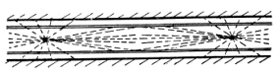
struction [sic]. The vertical prisms of the two-way refractors divide the light into two main beams. These beams are projected in
opposite ways so that when the two-way refractor is mounted, the street is lighted evenly in both directions.
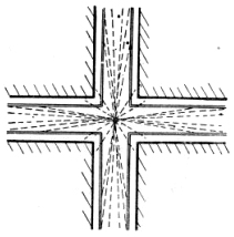
The vertical prisms of the four-way refractor divide the light into four beams 90° from each other, so that when it is mounted
in the centre of street intersections, even lighting is the result.
Obviously these refractors must be orientated properly with reference to the streets. To ensure proper orientation, three notches
are placed in the flange at fixed but unequal spacing. These notches engage lugs in the ring of the lantern which holds the refractor.
When the lantern is set in proper relations to the street the refractor fits in one position only. Consequently an inexperienced worker
can remove the refractor and replace it with no danger of incorrect orientation.
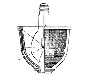
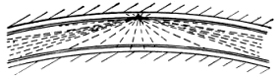
Part section showing Refractor
Assembly and action of
Horizontal Prisms
|
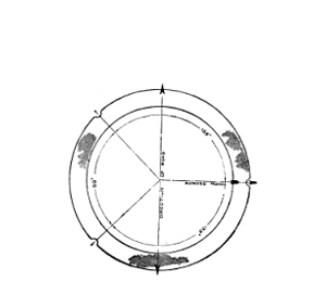
Diagram showing position of
notches in flange relative to
the direction of beams.
|
Dustproof Features
The smooth glass surfaces otuside and inside the unit afford little lodgement for dust and dirt; moreover, the
perfectly smooth surfaces can very readily be cleaned. For best results, however, all glassware should be thoroughly
cleaned at intervals to be determined by local conditions.
Lamp Positions
Holophane Refractors are designed to approximate the ideal distribution of light for uniform illumination over the
street. This ideal distribution varies according to the ratios of spacing to mounting height. At a spacing of 12 times
the height (which is the maximum spacing for good practice) the ideal distribution of light requires the maximum candle
power at 80° from the nadir, i.e. 10° below the horizontal. At a spacing 8 times the height, the required angle
of maximum candle power is 75° at 6 times the height is 70°.
Holophane Refractors posses characteristics advantageous to the production of these different distributions of light
with different settings of the lamp in the same refractor. The following table gives the lamp settings for the distributions
normally used.
Lamp Positions in Holophane Bowl Refractors
| 12-1 |
80 |
60 mm |
80 mm |
92 mm |
| 10-1 |
77½ |
58 mm |
77 mm |
88 mm |
| 8-1 |
75 |
55 mm |
74 mm |
83 mm |
| 6-1 |
70 |
51 mm |
68 mm |
74 mm |
A spacing ratio (spacing divided by height) of 8:1 is good practice for the symmertical type.
With the two and four-way Refractors, a spacing ratio of 12:1 is good practice. A ratio as low as 8:1 is less
common, though better in all respects except installation and operating costs. A spacing ratio of 6:1 is but
rarely justified.
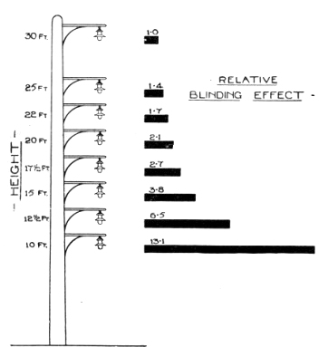
Mounting Height
In all street lighting it is desirable that the light source should be placed as high as possible in order to
minimise the blinding effect of glare from the lamp. 15 feet should be regarded as a minimum. 22 to 30
feet represents good average practice for main streets.
Spacing
When the lamp is set in the refractor to produce the maximum candle power at 80° from the vertical, the distribution
of light approximates the ideal distribution for uniform illumination if the spacing is 12 times the mounting height.
With a mounting height of 25 feet, this means a spacing of 300 feet. When the spacing between intersections does not
materially exceed 300 feet, this mounting and distribution of light with four-way refractors produces satisfactory results.
If the distance between street intersections is much beyonds 300 feet, an intermediate light should be supplied using a
2-way refractor. Such as intermediate light is necessary for first class service when the length between intersections is
more than 16 times the mounting height. Two intermediate lights are necessary for first class service if the distrance
between intersections exceeds 30 times the mounting height. If the spacing ratio is 12:1 in one direction and 8 or
10:1 in the other direction, the lamp should preferably be set for 12:1 i.e. angle of maximum candle power at
80°. The setting for spacing ratio 8:1 (75° angle of maximum C.P.) or spacing ratio 10:1 (77½° angle
of maximum C.P.) should only be used if the ratio in all service directions is not appreciably greater than these
values.
Amount of Light to Use
For residence districts 0.05 to 0.10 foot candles is a desirable standard to adopt. For arterial streets 0.12 to 0.15
foot candles. For main business thoroughfares and promenades from 0.2 to 0.5 foot candles according to the amount of
traffic and importance.
Required Generated Lumens per Unit to
Produce 0.10 F.C. Average Illumination
using Holophane Street Refractors.
| Symmertical distribution |
20.6 |
24.0 |
26.0 |
28.0 |
| 2 & 4-way distribution |
- |
17.0 |
20.0 |
22.0 |
|
Holophane Ltd
|
Elverton Street,
Vincent Square
|
London, S.W.1
|
Telegrams :-
"HOLOPHANE, SOWEST, London"
|
|
Telephones :-
"VICTORIA, 2491, 8258."
|
Back To Contents
|