|
|
|
|
|
|
|
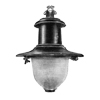
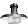
??? Lantern
Uses a bowl refractor designed for 400W MA/V lamps.
|
|
???
|
400W MA/V
|
GES
|
Top Entry
|
No Gear
|
1936 Advert
|
|
|
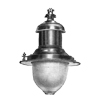
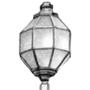
Lennox Lantern
For pedestal lighting. Uses a special ornamental refractor.
Illustration believed to be the Lennox Lantern.
|
|
???
|
???W GLS
|
???
|
Post Top
|
No Gear
|
1936 Journal
1936 Advert
|
|
|
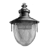
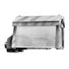
Refractor Panel Lantern
Uses a plate refractor designed for horizontally burning sodium lamps and
horizontally burning mercury lamps. Was used in the Westminster experiments of 1937.
It probably took 150W MA/H and 150W SO/H lamps.
|
|
???
|
??? SO/H
|
BC
|
Multiple top clips
|
No Gear
|
1936 Advert
1937 Paper
|
|
|
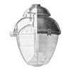
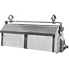
Refractor Panel Lantern
Uses a plate refractor designed for horizontally burning sodium lamps and
horizontally burning mercury lamps. Was used in the Westminster experiments of 1937.
It probably took 250-400W MA/H and 150W SO/H lamps.
|
|
???
|
??? SO/H
|
BC
|
Multiple top clips
|
No Gear
|
1937 Paper
|
|

|
Refractor Panel Unidirectional Lantern
Experimental unit used in the Westminster and Hangleton Road, Hove experiments.
Back refractor plate replaced by a reflector. Used with horizontally burning sodium lamps and/or
horizontally burning mercury lamps.
It probably took 250-400W MA/H and 150W SO/H lamps.
|
|
???
|
??? SO/H
|
BC
|
Multiple top clips
|
No Gear
|
1937 Paper
|
|
|
|

|
|

|
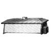
Cut-Off Lantern
Described as a cut-off lantern with a 150° non-axial distibution.
|
|
546/2/4562
|
500W GLS
|
ES
|
Top Entry
|
No Gear
|
1939 Programme
|
|
|
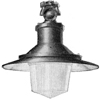
bi-way directional refractor lantern
 Also manufacturered as the
Siemens Bi-Way.
The refractor is 160° non-axial. It has internal
vertical prisms for the production of the main beams and a
smooth exterior, except for the bottom and a small area on
the footpath side where there are external prisms. Two
designs of this refractor have been produced: one where the
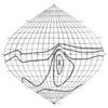
prisms are arranged to give a non-axial asymmetirc
distribution (as shown in the isocandle diagram) and an
axial asymmetric distribution. In the non-axial form
it is made in two sizes: the larger for 250W and 400W
lamps, and the smaller for 150W and 250W lamps. The lantern was used
in the Westminster experiments of 1937 and was fitted with a variety of
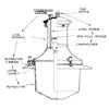
axial and non-axial bowls with different main beam angles. (Section diagram believed to be of
this lantern - found in 1939 paper).
This lantern embodies one of the most advanced and efficient types of bowl refractors,
designed for use with vertically-burning Mercury Discharge Lamps. The light control is obtained
by the use of patented reflector diffuser prisms carried on the inside of the glass, which
are so designed as to give a wide spread of light at relatively low angles and a more restricted spread at high
angles of emission, thus varying the width of the beams to match the angular width of the roadway
at different angles of elevation.
Two sizes are available, to suit Groups "A" and "B" installations, while the refractor bowl can
be supplied in alternative types to provide symmetrical, two-way axial, or two-way non-axial distributions.
The lantern is also available for side entry mounting.
|
|
561/2/4115
|
150W MA/V
|
ES
|
Top Entry
|
No Gear
|
1937 Paper
1937 Paper
1937 Advert
1938 catalogue
1938 programme
1939 Paper
1947 Book
|
|
563/2/4140
|
250W-400W MA/V
|
ES
|
Top Entry
|
No Gear
|
1937 Paper
1937 Paper
1937 advert
1937 Advert
1938 catalogue
1938 programme
1939 Programme
1939 Paper
1947 Book
|
|
563/22/4140
|
250W-400W MA/V
|
ES
|
Top Entry
|
No Gear
|
1937 Paper
1937 Paper
1937 advert
1937 Advert
1938 catalogue
1938 programme
1939 Paper
1947 Book
|
|

|
|
Bowl Refractor Lantern
|
|
564/2/4114
|
???W GLS
250-400W MB/U
|
ES
|
Top Entry
|
No Gear
|
1937 Programme
|
|

|
Cylinder Light Lantern
Introduced in 1939. Uses a new type of Prismatic Refractor to be used with horizontal
discharge lamps. To be used with horizontal light sources. The Refractor System
exercises control over the whole 360° of light flux emitted by the lamp, the major
portion of the flux being projected towards the road surface, and the
remainder being directed to an upper reflector designed for re-direction
at a high angle to the distant road surface. As a high peak of efficiency and
light control in the region of 85°.
|
|
???
|
400W MA/H
|
???
|
???
|
No Gear
|
1939 Advert
1939 Programme
|
|
|
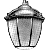
Dublin Lantern
First installed in Dublin in 1939. Fitted internally
with refractor glasses to control the distribution of light. All exterior metal parts of the lanterns are executed in bronze. A small number of
internal metal parts are executed in steel and aluminium alloy, the remainder being made of bronze. An anti-condensaiton
chamber is incorporated in the cast bronze head of the each lantern where it is suspending from the bracket.
This case head is connected to a second bronze casting which carries the glazed framework by means of an inner spider
of aluminium alloy and bronze. The space between the two castings is enclosed by a spun bronze dome. The entire
glazed framework swings clear on a hinge to give access to the internal refracting glasses and lamps. The external framework is glazed with
a specially selected diffusing glass of low absorption and high quality. The internal refracting units are comprised
of three pieces of prismatic glassware, two of which are hermetically sealed together in the form of an inverted bowl
with a cavity between its internal and external surfaces, together forming the upper member of the unit. The mouth of
the bowl is couvered by the third glass which is shaped like a deep dish. These units form a casing approximating
to spherical in shape around the light source or lamp. While practically the entire external surfaces of the refracting
units is smooth, the internal surfaces are cut into a series of prism groups which refract or bend the light
emitted by the lamps and direct it over the road surface as required through the external diffusing glass panels of
the lantern.
|
|
???
|
500W GLS
1000W GLS
1500W GLS
|
GES
GES
GES
|
Top Entry
|
No gear.
|
1939 Journal
1950s Catalogue
|
|
|
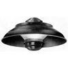
302 Lantern
Holophane 302 Street Lighting units have been designed in accordance with the requirements of
BS/ARP 37 for street lighting under war-time conditions. The general level of illumination provided by the
specification is 0.0002 ft. candle and nowhere on the road shall the illumination exceed 0.0004 ft. candle.
The B.S. specification publishes three sets of limiting vertical light distribution curves and any lantern used
for street lighting must be within the limits of these curves. The lanterns give a relatively uniform illumination
along the road and should not be spaced at less than 100' apart. The smallest GLS available is 15W which gives
a mean spherical candle power of 10, so that it is required to provide a fitting which will reduce the bare lamp intensity
at 75° by one-tenth and at 0° by over a sixtieth. This is accomplished in the 302 by a method which
is provisionally protected by patent No. 32075/39. The unit consists of a partially obscuring cylinder placed around
the source in combination with a secondary baffling member in the form of an inverted cone. The lower section of the cylinder
is so constructed as to allow the spcified intensity to be emitted at angles from about 65° to 85° to the vertical
while the function of the combination, cylinder and cone, provide the very subdued general intensity required at angles
below 65°. At the base of the cylinder is formed a flanged opaque cup which is fixed in a definite position
relative to the lamp filament. The fitting is completed with a bowl shaped reflector giving a cut-off at about
85° from the vertical. The unit gives a large area of low luminosity that is a distinct aid to vision.
|
|
302
|
15W GLS
|
BC
|
Top Entry
|
No gear
|
1940 Journal
|
|
|
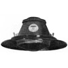
302 Lantern
An improved design after experiences during the winter of 1939.
The prismatic glass dish, smooth outside, having vertical diffusing prisms round the rim,
the remainder being rendered opaque on the inside, is mounted in a heavy guage steel sheet unit.
This is in two main parts, a body to which is attached an assembly consisting of a reflector
carrying the glasses with a perforated metal ring behind it and an inside white reflector all of
which is detachable in one piece by releasing three wing nuts. A cast top is provided which
is tapped to screw on the shade carrier lampholder wen required for existing lanterns. As an
alternative a sheet metal disc can be fitted for the conversion of existing lanterns. As a complete
lantern, a special cast top is avilable which is tapped ¾" gas, and fitted with a porcelain
lampholder. The unit takes 25W pearl lamp for the 20' mounting height or 15W pearl lmap
for 15' or 10'. The metal work is finished in black vitreous enamel.
|
|
302
|
15W GLS
20W GLS
|
BC
|
Top Entry
|
No gear
|
1940 Advert
|
|
|
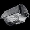
dilux lantern / 330 series
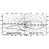
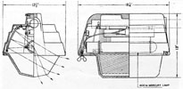 A new development (in 1947) in street lighting technique employing horizontally-burning Mercury Discharge Lamps, in conjunction
with a highly efficient optical system providing controlled cut-off (semi-cut-off) light distribution characteristics.
The high intrinsic brightness of the light source is shielded by the reflector assembly in the lantern hood, thus avoiding glare
conditions, while the combined reflector refractor assembly affords a controlled two-way non-axial distribution, promoting adequate road
surface and background brightness when installed in accordance with Group "A" requirements.
The lantern employs a 400-watt MA/V mercury discharge lamp, burning in a horizontal position and controlled by a magnetic
arc deflector to ensure satisfactory life and performance. The lamp is located within the body of the lantern, at which
position its high intrinsic brightness is shielded at those angles of view approaching the horizontal. Upward light emission
from the lamp is controlled by silvered prismatic reflectors which re-direct this flux into the lower prismatic bowl
at predetermined angles of incidence. The end sections of the mirror reflectors are provided with a specially designed
prism profile to utilise the light flux, which would otherwise be lost by regular reflection into the end castings of the
lantern. This feature also promotes uniform flashing of refractor bowl.
The shallow prismatic bowl is of heat-resisting glass construction, embodying a diagonal arrangement of prisms on the
inner surface, and a substantially smooth exterior for ease of maintenance. The prism design has been arranged to control
both the direct and indirect light emission from the lamp, and to afford a 2-way non-axial distribution with controlled
cut-off characteristics in the vertical plane.
A special feature of this distribution lies in the fact that a very steep gradient of candle-power values is
effected in the glare zone between 80° - 90°, and this factor materially improves the visibility for road users.
The combined optical system of top reflectors and lower prismatic bowl, ensures a high light output ratio, of which 95%
is directed into the lower heimsphere. The lantern body is constructed with hgih-grade silicon aluminium alloy to Specification
L.33, and other metals employed in the lantern assembly are cadmium plated to ensure resistance to corrosion in service.
The design of the unit, which is arranged for side entry, ensures that the weight of the lantern is evenly distributed
on the bracket arm over the entire length of the hood. Top entry can, however, be arranged as an alternative, where the
installation conditions are such that this form of suspension must be employed.
The lower reflecting bowl is carried in a hinged frame secured to the main body of the lantern by means of a single
captive wing-nut, thus allowing easy access to the lantern interior for maintenance and relamping purposes.
A notable feature of the design lies in the provision made to reduce glare conditions,
the lamp being located in the body of the lantern, thus shielding the intrinsic
brightness of the light-source at those angles of view which are more liable to
impair visibility. By a suitable design of a refractor bowl and top reflector approximately 90% of the light
is directed in a 2-way non-axial distribution in the lower hemisphere and the stray upper emission
is virtually eliminated. The smooth, well-shaped lines of the lantern are not only
pleasing to the eye, but have definite practical advantages in cleaning and maintenance.
|
|
???
|
250-400W MB/U
|
ES
|
Side Entry
|
No Gear
|
1947 book
1947 programme
1947 Journal
1951 book
1950s Catalogue
|
|
|
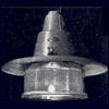
duo-dome lantern
These lanterns employ two-piece refractors so designed that the functional prismatic surfaces are internally sealed,
presenting smooth exterior surfaces, thus facilitating cleaning and maintaining optimum efficiency over longer periods.
Available in types suitable for Groups "A" and "B roads, and all installation requirements.
|
|
???
|
???W GLS
???W MB/U
|
???
|
Top Entry
|
No Gear
|
1947 book
1947 paper
1951 book
1950s Catalogue
|
|
|
|
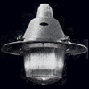
Bi-Way Refractor Lantern
|
|
???
|
???W GLS
???W MB/U
|
???
|
Top Entry
|
No Gear
|
1951 book
|
|
???
|
???W GLS
???W MB/U
|
???
|
Side Entry
|
No Gear
|
1951 book
|
|
|
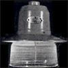
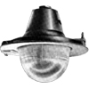
single-piece refractor lantern
Simplicity and efficiency, together with low initial and operating costs, are the primary features underlining the
design of this refractor lantern series. Available for lamp ranges suited to both Groups "A" and "B" installations,
together with alternative refractor designs for symmetrical and two-way non-axial distributions.
|
|
211
|
100W GLS
???W MB/U
|
BC
|
Top Entry
|
No Gear
|
1947 book
1951 book
Public Lighting #80
1950s Catalogue
|
|
|
|
|
|
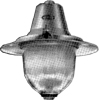
Two-piece Bowl Refractor Lantern
|
|
???
|
100W GLS
|
BC
|
Top Entry
|
No Gear
|
1950s Catalogue
|
|
|
|
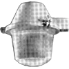
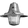
310 Lantern (Side Entry)
|
|
???
|
???W GLS
???W MB/U
|
???
|
Side Entry
|
No Gear
|
1950s Catalogue
|
|
|
|
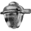
310 Lantern (Top Entry)
|
|
???
|
???W GLS
???W MB/U
|
???
|
Side Entry
|
No Gear
|
1950s Catalogue
|
|
|
|
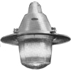
320 Lantern (Side Entry)
|
|
???
|
???W GLS
???W MB/U
|
???
|
Side Entry
|
No Gear
|
1950s Catalogue
|
|
|
|
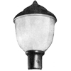
320 Lantern (Top Entry)
|
|
???
|
???W GLS
???W MB/U
|
???
|
Side Entry
|
No Gear
|
1950s Catalogue
|
|
|
|
|
|
|
|

|
|
|
|
|
|

|
|
|
|
|
|


