
|
|
|
ilp archive : glasgow 1945
|
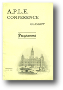
Programme
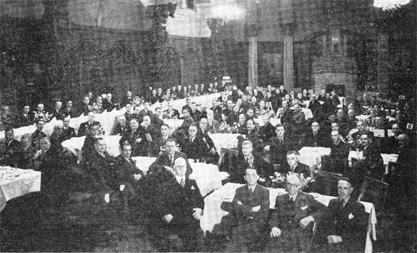
Annual Conference at Glasgow
September 11th-13th, 1945
Was considered to be the postponed conference from 1939.
Limited to three days, but included papers, demonstrations of Glasgow's centrally controlled street lighting and
an exhibition by manufacturers.
Planned exhibitors and stand numbers were:
(1) Gowshalls Ltd.,
(2) Siemens Electric Lamps And Supplies Ltd.,
(3) British Sangamo Co. Ltd.,
(4) Metropolitan Vickers Electrical Co., Ltd.,
(5) Keith Blackman Ltd.,
(6) Concrete Utilities Ltd.,
(6a) William Edgar & Son Ltd.,
(7) Venner Time Switches Ltd.,
(8) Automatic Telephone And Electric Company Limited,
(9) British Foreign and Colonial Automatic Light Controlling Co. Ltd.,
(10) The Electric Street Lighting Apparatus Co.,
(11) Philips Lamps, Ltd.,
(12) The Brighton Lighting And Electrical Engineering Company, Ltd.,
(13) Record Electrical Co. Ltd.,
(14) W. Parkinson and Co.,
(15) Holophane, Limited,
(16) William Sugg And Co., Ltd.,
(17) Engineering And Lighting Equipment Co., Ltd.,
(18) REVO Electric Co., Ltd.,
(19) Edison Swan Electric Co. Ltd.,
(20) Poles (1938) Ltd,
(21) Falk, Stadelmann and Co. Ltd.,
(22) The Horstmann Gear Co., Ltd.,
(23,24) The General Electric Co., Ltd,
(25) The British Thomson-Houston Co. Ltd.,
(27) Lighting Trades, Ltd. and
(28) Hobbs, Offen & Co., Ltd
Abstract: Descriptions of lanterns and equipment displayed by
Siemens Electric Lamps And Supplies Ltd.,
British Sangamo Co. Ltd.,
Metropolitan Vickers Electrical Co., Ltd.,
Keith Blackman Ltd.,
Concrete Utilities Ltd.,
William Edgar & Son Ltd.,
Venner Time Switches Ltd.,
Automatic Telephone And Electric Company Limited,
British Foreign and Colonial Automatic Light Controlling Co. Ltd.,
The Electric Street Lighting Apparatus Co.,
Philips Lamps, Ltd.,
The Brighton Lighting And Electrical Engineering Company, Ltd.,
Record Electrical Co. Ltd.,
W. Parkinson and Co.,
Holophane, Limited,
Stanton Ironworks Company Ltd.,
William Sugg And Co., Ltd.,
Engineering And Lighting Equipment Co., Ltd.,
REVO Electric Co., Ltd.,
Edison Swan Electric Co. Ltd.,
Poles Ltd,
Falk, Stadelmann and Co. Ltd.,
The Horstmann Gear Co., Ltd.,
The General Electric Co., Ltd,
The British Thomson-Houston Co. Ltd.,
Willey And Co., Ltd.,
Sordoviso Switchgear Limited and
Radiovisor Parent Ltd..
Adverts:
Radiovisor Parent Ltd.,
Gowshall Limited,
Siemens Electric Lamps And Supplies Ltd.,
British Sangamo Co. Ltd.,
Stewarts And Lloyds, Ltd.,
Metropolitan Vickers Electrical Co., Ltd.,
Walter Slingsby and Co., Ltd.,
Keith Blackman Ltd.,
Concrete Utilities Ltd.,
William Edgar & Son Ltd.,
Venner Time Switches Ltd.,
Automatic Telephone And Electric Company Limited,
Philips Lamps, Ltd.,
Automatic Light Controlling Co. Ltd.,
The Electric Street Lighting Apparatus Co.,
Standard Telephones And Cables Ltd.,
The Brighton Lighting And Electrical Engineering Company, Ltd.,
Record Electrical Co. Ltd.,
W. Parkinson and Co.,
Holophane, Ltd.,
Stanton Ironworks Company Ltd.,
William Sugg And Co., Ltd.,
Engineering And Lighting Equipment Co., Ltd.,
The Gas Council,
REVO Electric Co., Ltd.,
Edison Swan Electric Co. Ltd.,
British Electrical Development Association,
Poles Ltd,
Poles Ltd,
Falk, Stadelmann and Co. Ltd.,
The Horstmann Gear Co., Ltd.,
The General Electric Co., Ltd,
The British Thomson-Houston Co. Ltd.,
Foster And Pullen Ltd.,
Lighting Trades Ltd. and the Welsbach Light Co., Ltd.,
Willey And Co., Ltd.,
Sordoviso Switchgear Limited,
Hobbs Offen And Co. Ltd.,
C. H. Kempton and Co., Ltd.,
Standard Telephones And Cables Ltd. and
The General Electric Co., Ltd.
Provisional papers (as planned in Public Lighting #37):
-
- Tuesday, September 11th, 1945
- Annual General Meeting
- Presidential Address by Mr. E. J. Stewart, M.A., B.Sc. (Inspector Of Lighting Of Glasgow)
- Prize Winning Paper
- Wednesday, September 12th, 1945
- Glasgow's Street Lighting by Mr. J. M. Ward
- Lighting Of Bends And Junctions by Mr. F. F. Middleton
- Address on work for forthcoming B.S.I. Specification on Street Lighting by Dr. J. W. T. Walsh
- Thursday, September 13th, 1945
- Engineering Principles In Lantern Design by Mr. J. G Christopher and Mr. J. S. Smyth B.Sc.(Eng.)
- The Commercial Aspect Of Public Lighting by Mr. E. S. Harris
A competition was held for papers. The winner was to be read at conference. Having picked the winner and runner-up
(The Relation of Public Lighting to Safety on the Roads by Norman Axford and
Photometry in Relation to Street Lighting by F. M. Hale) it was decided there wasn't time to read them. Instead the papers
were published in Public Lighting.
There was also a discussion concerning the proposed B.S. Specification for street lighting. The introduction
and discussion were included in Public Lighting, Vol. 11, No. 40. January-March 1946
|
|
Presidential Address
Mr. E. J. Stewart, M.A., B.Sc.
Inspector Of Lighting Of Glasgow
Keywords: Lighting: ARP, Lighting: Authority Organisation, Lighting: Future, Lighting: History, Lighting: Levels, Lighting: Theory, Lighting: Users
Tuesday, September 11th, 1945
A limited reproduction of the paper was published in: Public Lighting, Vol. 10, No. 38. July-September 1945
Abstract: The future of public lighting with reference to lessons learned during the war, and the 50 year post-war plan issued
for Glasgow. Includes first references to proto-motorways (arterial routes with roundabouts and no local traffic).
We may congratulate each other and our Association on the great number of delegates attending this Conference. It shows
that those concerned area all determined to bring back public lighting into its proper place, prepared for renewed audience,
and that we are seeking to learn all that we can about the subject.
Thanks
This is the third Presidential Address to the A.P.L.E. I have prepared:
the first (Glasgow 1939) considered noticing
and noticeability in lighted streets, criteria used, especially by the public in judging street lighting, the importance
of the pedestrians and local residents, as well as of the drivers;
the second address (London 1943) reviewed some effects of the war on street lighting
with an eye to post-war conditions and asked a lot of questions; today I draw attention to some present features of
our local lighting, which has not yet fully reached post-war status and the incidence of some post-war town planning
on our lighting problems and programmes.
A Modified Conference
I express regret that the Conference in Glasgow in 1945 is a pale reflection of that planned, and lost, in 1939. There
is a decline in the number of events and the quality and variety of public lighting to be seen.
Restrictions on street lighting have officially been removed since 15th July and some towns have lit right up to pre-war
standard. Some are beyond pre-war because they had new installations completed since the winter of 1938-39 and have only
been waiting for the black-out to be lifted.
In Glasgow, the output from gas lamps at maximum consumption pre-war was modest and so we have not intended to
scrimp seriously with these. The relatively few tram routes, bus routes and other main thoroughfares not yet converted to
high-mounted electric lighting have resumed their 4-light or 3-light burners. In electrically lit streets, the war taught
us how to substitute lamps of lower wattage with relative ease and we are still saving in this way.
Finance
During the war wages continued to rise; but this rise was counterbalanced by a fall in the cost of
gas and electricity through greatly diminished consumption. Now increases in wages, gas and electricity
have all to be added if we are to give merely pre-war service. For use to attain to full pre-war standard
of lighting, it would be necessary to spend about £50,000 or more on gas and electricity, or the equivalent
of one penny rate. There is a maximum figure for the lighting rate which can be levied in Glasgow.
The additional penny would bring us dangerously near that limit.
100 Yards Visibiltiy
It would be deplorable if saving on public lighting were to reduce the safety of the lieges.
From the knowledge gained during the war, where 0.2 f.c. was the maximum, from sources at 25 ft., it was
a revelation. 100W tungsten lamps at the same height and spacing (where 300W or 500W lamps were used),
gave visibilities of 100 yards and even well over. The associated aim of satisfactory street lighting
was also obtained that drivers drove without headlights. I do not suggest a restriction of light-output.
It shows the benefit of high mounting; and the same experiences show how low mounting tends to glare
and patchy lighting.
Limits
Is an upper limit desirable? To what? The: (a) public lighting rate; (b) the consumption of gas or
electricity; (c) to the lumens per 100 foot of road, or the illumination of the road surface, or the
brightness of the road surface or (d) to the visibiltiy and safety of road users at night. Cost are double
what they were; but people pay double for other services of pre-war standard and less; and they must
expect to pay for public lightig also.
Complaints
Complaints were few through the star-lighting years; but they multiplied rapidly when relaxed (moon-lighting)
was introduced. As soon as a street or court gets lighting which it never had before, or it gets better
lighting, then there is a cru from elsewhere for the same. The features stressed in the 1939 address have
not been invadlidated by war-time experience.
Limitation Of Light
There may be a limit to serviceable lumens. But there are many miles throughout, where the design can be improved,
but there is not enough light. Must we consider fuel scarcity as permanent? Whether or not, ought we to light
for more than sheer "safety visibility?" There is the practical question: "If we have only a fixed sum
to spend on light, how shall we spend it?" It seems desirable to light all the streets to safety grade before
entering upon display lighting.
High Mounting
I would give the benefits of this feature, prescribed for "traffic routes", to all streets in which there
is traffic worth considering, remembering the importance of light for policing. In Glasgow, you may see
high mounting applied to 100W, 300W and 500W tungsten lamps, mercury and sodium discharge lamps; in dual
carriageway and single carriageway main roads; in residential streets; in still narrower back-lanes in
the centre of the city with much need for police supervision all night. You may see it with directive and
non-directive lanterns, with various degrees of cut-off or none. You may see it obtained by special lighting
poles, by extension-pieces on tramway poles, by span-wires between poles or buildings, and by long brackets
attached to buildings.
Our policy is essentially to provide high mounting. It was by reason of this and of the accompanying
overhead wiring and central control that we were allowed the full relaxation to 0.2 f.c. at 17th September
last year for some 18,000 lamps.
If we restrict the lumens, those provided are more effective sent from high sources. If the lumens are generous,
their effective use is feasible only with high mounting, in order to give good distribution and relative
freedom from glare. In a narrow side street, the tall standard may appear out of place, so the mounting height
is near 20'.
Glare
300W lamps at 25': can be changed for 1000W lamps or use of directive equipment with 300W to produce a brighter
field and greater visibility. 60-100W lamps at 10', 13½' or 15': if changed either way will make visibility worse.
There is an absence of a glare-sense among the lay public: a resistential bus route had its lighting changed
from 100W tungsten in plain vitreous enamelled reflectors to 45W sodium lamps with mirrors mounted higher
at 14½' - it was agreed the installation afforded complete brightness but was uncomfortably glaring
to the point of introducing disability. This would've done excellent work from 20'. However, a letter of
thanks was received from a resident.
High Mounting - Disadvantages
Higher capital cost for poles and attachments (but use overhead instead of underground cable to reduce costs);
larger surface of column to keep painted (unless using concrete); special equipment required for access to
fit lanterns etc., to renew lamps, or mantles, or clean.
High Mounting and Damage
Wilful damage has grown these recent years into a major problem. In a number of streets, high mounting
offers the only hope of keeping lamps lit.
Planning
Concerted planning, for town or country, is going to have much more influence upon the form and layout of
roads and of the buildings which they serve than in the past, and so upon our own work, the lighting of
roads.
Glasgow 50 Year Plan
Glasgow has suffered very little from war-damage, and so there is no easy lead in that way to the radical
alterations which modern traffic demands. Various planners have suggested ways to overcome the difficulties.
The most recent, most offical, and perhaps most sweeping of such plans, is put forward by the City Engineer,
Mr. Robert Bruce, in 1945. Many have only thought five or ten years after the war. It may be worth
considering a road-making programme so extensive that it looks 50 years ahead.
Looking Ahead
The planning of roads and buildings and spaces for a whole city or district involves so much preparation
and work that it will take years of time. The lighting of roads is perhaps different and cannot come first.
The new road must be planned before we can even plan. "See your road before you fix your lamp positions!"
Roads And Transport
A first report called 'Roads And Transport' has been published. It remakes the centre of the city and
there is a classification or segregation of roads with three chief classes:
- Arterial: Will carry fast motor traffic only. Fenced to prevent access by persons or animals.
No traffic signals, with intersections confined to roundabouts at other arterial or sub-arterial roads.
No pedestrians or pedal cyclists but have subways. No footways. These would include radial arterials
following the lines of existing roads, also an inner and outer ring arterial, involving two new bridges over
and a new tunnel under the Clyde.
- Sub-Arterial: Would collect mechancially-propelled vehicles from the major local roads and lead
them to the arterial road system. They would be generally existing main roads adapted to meet the requirements
of their new classification. Most would have to be widened. The intersection with arterial roads will be at
large roundabouts. Pedestrian barriers will be used on great extents on sub-arterial roads and an 'all-red'
period used in the traffic sugnals for the user of pedestrians, including an extended 'amber' period.
Public service vehicles will lift up and deposit passengers at stops on sub-arterial roads. Pedestrian
subways will be provided at suitable points.
- Local: Their primary function is to provide access. Would be in each community area. The minor feeding
the major, which in turn, feed the sub-arterial. The number of junctions with sub-arterials will be
a maximum.
The pedestrian of the 1939 address may be segregateed off certain highways altogether.
Classes Of Road Lighting
The MOT Report has recommended only two classes of road or street lighting. The proposed new Street Lighting
Specification follows the same direction. In roads and streets as they are, this distinction is
insufficiently comprehensive and also that, if Group A lighting is the better, we ought not harshly to
restrict its application. Is the dual classification sufficient for the lighting of the three classes of
city roads in the future? And for the complications of separate one-purpose motor highways, roads carrying
cyclists and pedestrians, separate electric vehicle tracks, subways, separate shopping and residential
streets.
Narrow Carriageways
Bruce's proposal features narrow roads. "The width of a local road shall be that which suits the
purpose of the road. Thus, if a bus service is to run on a local road, then the road width will be made
adequate for such use. If the local road is only for the use of private cards and tradespeople its width
will be to correspond and may be as little as 16' between kerbs." May existing local roads are too wide.
Redundant roads may be removed altogether; it is suggested that 12% of the whole area of Glasgow
is given over to roads, mostly local roads, many of which are quite unnecessary.
Effect On Lighting
If there is to be segregation of function among roads, some segregation of function and divergence
of form are suggested in the types of road lighting. If new roads are to be formed then much of the
existing road-lighting plant will have to be removed. Existing roads and streets may remain but change their
classification and perhaps their form.
Continued Programme
We must, as soon as money, labour and material are again available, erect some lighting in the new streets
of housing areas where there have been none. We must resume the improvement of lighting in busy thoroughfares.
The 50-Year Plan does not affect the previous estimate of the work of this Department for the next five or
ten years:
- The lighting by high mounted units of additional bus routes.
- The lighting of new streets in housing schemes.
- The lighting of new temporary approaches to temporary houses.
- The bringing up to MOT Report traffic route standard the lighting on tram routes and Class A roads.
- The installation of further central control to street and stair lighting.
Arterial Road Lighting
Special care must be taken with the lighting of such roads. Are different types of lighting to be
used as distinctions between arterial and sub-arterial and local roads? This is more fundamental than
"traffic routes" and "other roads". We may look for continuous lighting on the arterial or other connecting
roads. In due course, we may expect much longer intervals to be filled in with static lighting along the
roads for fast motor traffic only; if not between London and Glasgow at least between Glasgow and Edinburgh.
Such rural stretches have their special problems of supply and maintenance.
Dual Carriageways
We assume there will be no more single carriageways 50' to 60' wide. These are difficult to light from the
sides and the three rows suggestion of the MOT Report is hardly practicable, unless there's a central
reservation or a succession of central islands. The proposed narrowing would make that central band of
darkness or dimness more amenable.
Intersections
The proposed reduction of the number of intersections should simplify the lay-outs of our lighting.
However, many of these intersections will be much more complex than those at present provided. The
roundabouts on the arterial roads are not the "simple" formatiosn with central island prevalent today.
Roundabouts
We are now faced with two-(or more) strey street junctions. There will still be the problems of lighting the
incoming and outgoing ways; there will be the new feature of the ramps leading up to and down from the raised
roundabout.
Covered Ways
These are so far uncommon forms. Who is going to be responsible for the ligthing of the underground tram
and electric railway stations: the transport undertaking or the local public lighting authority? There is
also going to be widespread lighting at roundabouts and subways. This will probably involve the use of
lamps affixed to ceilings and walls. Parts will have to be lit by day as well as by night. One 'subway'
example already exists with the Central Station Bridge: this has been lit from the roof with some of the
usual street lighting lanterns; but Maxwell Street under St. Enoch Station was recently converted from
ordinary square lanterns on brackets to wall fittings with refractors.
Bridges
When over-bridges get special lighting it is frequently for appearance. The usual bridge presents no
unusal problem for lighting except for foundations. For shorter bridges this is avoided by keeping
lighting standards beyond the ends of the bridge structure proper.
Lighting For Amenity
There are planned more public spaces around the new public buildings, of tree-lined avenues,
of riverside and seaside promenades, where lighting will be sought as a gracious amenity. It will
be admired for its own sake.
Trees
Trees are promised for all classes of roads and public spaces. However, trees are alright in their place -
apparently as far from our lamps as possible. Trees on the roads do offer problems in getting the light
along it and even just across it.
Quick or Slow Change
With such a large plan should the obvious necessary improvement of existing street lighting be
quick or gradual. Some cities rush it through, borrowing for the large capital costs, placing the
whole work in one or a few contracts. In Glasgow all erection of lighting is paid for from the
revenue of the current year. It takes longer but avoids payment of interest. It doesn't leave us with
a scheme of one kind which may be out of date before it's paid up.
Regional Planning
This Report deals almost solely with the City of Glasgow inside its present boundary. Mr Bruce does
suggest some form of regional control in transferring one portion of a burgh to another for
suitable treatment as a "community area."
Government And Local Authority
This concerns the relations of the National Government and the Local Authorities in the planning and
control of public lighting, and in the payment of it. There must be some moderate course producing
coordination and reasonable uniformity without the commonly feared stultification of local knowledge
and enterprise by a remote and merely Treasurey-minded control. There are dangers in over-centralisation
of administrative control of public lighting.
|
|
Glasgow's Street Lighting
J. M. Ward
Assistant Insepctor of Lighting, Glasgow
Keywords: Lighting: ARP, Lighting: Columns, Lighting: Control, Lighting: Funding,
Lighting: Legal, Lighting: Maintenance and Lighting: Management.
Tuesday, September 11th, 1945
A very brief summary of the paper was published in: Public Lighting, Vol. 10, No. 38. July-September 1945
Abstract: Description of the Glasgow street and stair lighting: from the actual installations themselves, the
lanterns (and their wartime modifcations), the control systems (including thorough descriptions of impulse and
cascade relays), the premises, the plant and maintenance, the finance allocation and the number and responsibilites
of the staff.
There are 685 miles of lighted streets and 25,000 common stairs. Street and stair lighting is the responsibility of
the local authority by the Police Act of 1866, and the appointment of Lighting Inspector is covered by the
same act. This involves the lighting, extinguishing and maintenance of 126,500 lights, varying pre-war in consumption from
.7 cu. ft. of gas to 1000W electric.
Following thre relaxation of the Lighting Restriction Order in September 1944, Glasgow was probably the best lit of
the larger towns in Great Britain because:
- (1) The extensive central control system.
- (2) The general use of 25' mounting heights in the main streets.
- (3) The long standard policy of a simplified lighting fitting.
300 miles were lit to the permitted 0.2 standard.
The Glasgow Standard Lantern (mounting height 25') had been fitted with BS/37 Starlight fittings. Changing over simply
meant removing the ARP fitting, fixing a Goliath to B.C. adapter taking the 100W Pearl lamp, which gave the 0.2 required.
In the installations with the small Glasgow Standard Lantern or St. Mungo 15' fitting were fitted, a 60W lamp with an
E.S. cap toook the place of the ARP fitting.
Labour costs have increased to such an extent that if gas and electric consumpts ruling before the war, taken at
increased prices, as also new work and conversions at the higher costs, then the resulting budget could not be met.
The results certainly made one think seriously of pre-war wattages. Streets which before black-out days gave amazingly
good visibility with 300-500W lamps have amazingly good visibility with "moonlight" 100W.
Mounting Height And Spacing
The MOT specification (of 25' mounting height spaced at 150') had been pretty much the practice since 1908.
The installations at that time had high cast iron columns which with growing motor traffic were considered dangerous
and repalced with the present 37'6" steel poles. Since the beginning of the war 19300 of the 9' cast iron pillars
were smashed and sent as scrap; 100 of the 37'6" steel poles were hit and badly bent, returned to the makers, straightened
and put back into service.
Many interesting examples of span mounting with two units per span can be seen, employing the 15" St. Mungo
reflector with no glssware. In such installations the mounting height drops to 22'. Committed to overhead cables,
the Department cannot use the lower mounting height suggested (at 15') but it is generally agreed that low-mounted
installations are unsatisfactory - although circumstances, generally financial, may make them "evils to be borne."
However, many large housing schemes completed between 1920-1930 were lit with 9' cast iron pillar to which was
fitted a 12" St. Mungo fitting giving 10'6" to light source.
Spacing is at the 40 yards recommended but some older installations are spaced at 50 yards.
Concrete columns were tried at a war-time housing scheme in Penilee for the first time. These are used with
overhead cables. This type of columns is enjoying popularity at the moment.
Glasgow Lantern
Used with 300-1500W GLS lamps - presently being used with 100-300W lamps with Goliath-B.C. adapters.
It has evolved over the years. It is designed for maintenance from a tower wagon. All lanterns are fixtures,
raising and lowering gear being used only in a few positions where the tower wagon can't get. There are over
9000 in use. The lantern has a 24" external reflector and is fitted either with a 12" pear-shaped clear globe
or 12" x 5" opal cylinder - the latter gives best results when the 500W lamp is used. Focussing is by means
of a movable bridge-plate carrying the holder, travelling on three vertical rods. On this bridge plate is
a fuse which has been introduced to cut odwn the number of dark sections - where one lamp takes out the circuit
fuse and darkens up to 15 lamps. The largest is the G.3 lantern. There are a large number of 28' poles giving
20' to light source which use the smaller G.2. lantern - this is used with 150-200W lamps - but on the present
"economy" lighting it uses a 60W E.S. lamp. It can be used with an 8" pear-shaped glboe or a 8"x4" deep opal
cylinder. (Stocks are low as a fire in the warehouse destroyed thousands). In many cases, 15" St. Mungo fittings
have been installed which have no glassware.
Control System
In Glasgow which covers 39,725 acres with 675 miles of lighted streets and a switchable load of over 4000kW
a central master switch to turn everything on would be absurd. Apart from war emergencies, the main argument
for a central control system is labour saving and consequent financial saving. At this stage, no case is required
for collective control and it is on this score that gas finds itself at the greatests disadvantage.
The Glasgow plan has been to divide the city into seven control areas and in each of the existing five
Control Stations switch boards are in operation controlling large numbers of street and stair lamps.
The cabling is overhead and under the Department's care and maintenance. Control was developed on the relay system.
A superimposed system has been looked at (after a demonstration in Lichfield in March 1938) but the system has
problems scaling up to Glasgow's needs.
For street lighting and traffic signs they have close to 1000 relays in use. However, they have not reached the
same level of standardisation as with lanterns. Patrick Division was fitted with cascade type relays but several
break-downs resulting from thuderstorms devided a change of policy. Switch wire relays were introduced but this
work was interrupted by the war. Fearing problems with switch wire relays, such as bomb damage to control wires
leaving street lightings on, and safety being the first consideration, the cascade system was re-introduced.
Cascade Relays
These give good service but the system suffers from thunderstorms and on one occasion 15 relays were
destroyed. Noisy relays form a frequent cause of complaint. Uneven mounting is
a common cause of trouble, developing when the teak panel on which it is mounted, warps.
Coil wear due to the long periods of energising is common, but the most serious problem
is one relay failing bring down all the installation ahead.
Impulse Relays
This involves passing the current for a few seconds, energising the coil long enough to
close the circuit. It introduces more mechanical operation than with the other types.
Improvements, found during testing, are:
- (1) Housing: It has been operated mounted on the teak panel in the section box
resulting in dust settling where oil is used. Dust also found its way into mercury pots. A suitable
form of covering is being devised.
- (2) Mounting Experiments are proceeding with other types of mounting. Warped
mounting panels cause misalignment of the trigger road.
- (3) Oiling A very little of the right kind of oil is essential at specified intervals.
- (4) Toggle Design Differences in curve and dimensions will result in failure.
The policy of the Corporation is to convert gas lighting to electric as finance permits. There have been no new
gas installations.
There are still a large number of ARP fittings with their bottom cup removed.
Stair Lighting
Gas Lit Stairs
There are 17,000 closes lit with gas. Number of lights per close varies from 1 to 7 but 85% have four lights.
All lights are connected direct to the rising main for the domestic supply. There are 64,500 gas burners in use.
The lantern has a small cone on the roof and the gas is ignited by the lamp lighter placing the torch flame above it.
Electrically Lit Stairs
There are 30,300 electric stair lights in 8000 closes and stairs. The fitting is extremely simple. There is a special
stair lighting circuit run from the Supply Authority fuses. The lighting is operated by a key and when switched on, the lamplighter can
check if all lamps are lit by the brightness of the green pilot or indicator lamp. There is also an arrangement whereby the blowing
of the circuit fuse automatically brings in a standby fuse, keeping the stair lit, with the exception of the defective lamp - and the
red pilot light is lit which indicates that the emergency circuit is now running. Quite an number of the stair lighters
have "all-electric" beats and are responsible for 400 lights. If all stairs were electrically lit a reduced staff of
only 240 would be required as against the present 650.
Premises
Langside, or the Southern Control Station, was the model for other Divisional stations. There is a muster hall
(for 80 lamp lighters), Superintendent's office and storeroom at the front of the building whilst at the rear
is a large workshop, electrical foreman's office, storeroom, garage and large yard. The number of Divisional
Stations has been reduced to 11, with a further reduction to 7 planned. The Govan Station will have extensive workshops
where the mtal spraying plant will be installed which can handle the 37' 6" poles, extension pieces, brackets and
scroll work.
Plant And Maintenance
Much of the plant requires painting and overhaul. The painters were fully employed on ARP signs and fittings and
when they could be freed, they had to concentrate on traffic signs. The Glasgow atmosphere is deadly on unprotected
iron and steel.
The first square gas lanterns were made from black iron or tinplate and these were useless in the city atmosphere
All subsequent lanterns were made from copper right until the outbreak of war.
During the war, sheet iron was the only metal available for the numerous special First Aid, Casualty Hospital,
and ARP signs. Although given two coats of protective paint they had to be brought in for repair.
The overhead cabling method entails the use of a very large number of clamps round the poles carrying the
insulators. It is a frequent experience on examining an installation after a few months to find badly disfigured
corroded clamps and bolts. Consequently, an order was passed to the workshops that all work for exterior use
must be treated by metal spraying.
Finance
The total figure is £440,500. Wages are a very heavy item. Change-over budget (from gas to electricity)
is the left-over from maintenance and new work - so gas and "Leeries" (lamp-lighters) will probably be seen
in Glasgow for the next twenty years or so. The problem with stair lighting is even worse: out of 95,000 stair
lights, 30,300 are electric. The Lighting Department cannot force a change of illuminant as it's up to the
proprietor to provide a supply (as per the 1866 act) - and the proprietor would have to meet the cost of change.
Staff
The pre-war staff totalled 1,152 and 650 left for service or war work. Stair lighting took the biggest hit.
It has been maintained by employing women, and there are 450 at work as present.
Appendix: Weaver v. Corporation
Details of a court case where Weaver drove into a 'pillar of fire' which was not illuminated due to
a thunderstorm overloading circuits and causing fuses to blow. The court found in favour of the Corporation
under Vis Major.
|
|
Lighting Of Bends, Junctions And Roundabouts
Francis F. Middleton
Keywords: Lighting: Distribution, Lighting: Theory
Wednesday, September 12th, 1945
A very brief summary of the paper was published in: Public Lighting, Vol. 10, No. 39. October-December 1945
Abstract: Shows how the lighting of pavements and backgrounds is more important than uniform road brightness when
considering pedestrians about to cross the road. Details how this situation is even more important for bends, junctions
and roundabouts. Describes a new form of light distribution which will light these areas more effectively.
The success of a lighting installation depends on the amount of money the authorities are prepared to spend; and the
ability of the designer to utilise his knowledge with intelligence in the selection of the "lighting medium" and to relate
it properly to the surfaces he has to illuminate. He must determine the type of source, the character and intensities of
the light it distributes, and the position in which it is placed in relation to the various types of background.
The Final Report on Street Lighting (1937) clearly and concisely states the requirements of the "lighting medium": "We
accept the view that, except in congested traffic, objects on the road at night are almost always seen in silhouette as
dark objects on a bright background, and that if other conditions, such as glare, remain unchanged, visibiltiy will,
threfore, be the greater the higher the brightness of the background and the lower that of the object. Although these two factors
are not the only ones involved, it follows that the distribution of light from the fittings should be designed primarily to
produce uniform and high a background brightness as possible, subject to the avoidance of undue glare, whilst at the same
time maintaining as high a contrast as possible between objects and their background. The background includes not
merely the carriageway and footway surfaces, but other surfaces such as those of buildings or fences against which objects
may be seen."
When a light source is mountned to illuminate a carriageway, a substantially brighter region is produced on the surface by
semi-specular reflection between the observer and the source than on other parts of it equally illuminated. The width and
length of this brighter region varies with the nature of the surface material, the angle of the incident light and the
angle of view. The tendency is to give too much importance to the formation of these bright regions and the merging of the
reflections from successive sources, and too little regard to those other parts of the backgrounds which should also be
as uniform in brightness as the carriageway.
The backgrounds are too varied to attempt to evaluate their reflection rations. Trees and hedges require considerably more
light to equal the brightness of a light-coloured building. Those boundaries adjacent to the carriageway at bends and junctions
should be provided with a brightness approximately equal to that of the carriageway.
If we desire to produce for a specified point of view an appearance of uniform brightness on any surface then we must
compensate for the disparity by graduating the light intenstiy which is reflected by them. This can be applied to the
lighting of bends and junctions and the success will depend how efficiently the light is distributed by the lantern in
relation to the types of surfaces.
Using diagrams of straight roads, bends and T-junctions, it is shown that
a very small part of road brightness, as compared with pavement brightness,
is involved with exposing pedestrians ahead. It is proved to be essential
in these cases that some form of background should be illuminated at all
bends and junctions, and if none exists, it should be created specially for
this purpose. Therefore lanterns should be created which explicitly light
the 30' of roadway, 10' of pavement and 10' of height of the building on
each side of the road.
|
|
Engineering Principles In Street Lighting Design
J. G. Christopher and J. S. Smith B.Sc. (Eng.)
Keywords: Lighting: Design, Lighting: Luminaires, Lighting: Maintenance,
Lighting: Materials
Thursday, September 13th, 1945
A paper was published in: Public Lighting, Vol. 11, No. 40. January-March 1946
Abstract: This paper has traced the development of present practice, and has endeavoured to show how some of the problems
which arise have been approached; but no attempt has been made to prophesy the trend of future design or to classify types
of lanterns. The rapid progress of modern research will always make dogmatic opinion dangerous; moreover, many desirable
developments are precluded at present day by their expense. Netherless, whatever conditions may arise in the future, the
broad mechanical requirements of a street lighting lantern will remain unchanged for many years.
Foreward: First written in 1939, the original paper analysed the fundamental
mechanical requirements of a street lighting lantern, and to show how these requirements were
satisfied in the equipment available at the time. The past six years have been notable for
many atonishing engineering achievements, and it could well be that new materials and processes
now available might considerably modify the conclusions reached in 1939. However, no startling
changed need be expected. The economic limitations for street lighting still apply, and
there wil be no change from the pre-war technique of "apply" light to the road surface. Lamps
for Service requirements do not lend themselves to street lighting so the lamps available
in the pre-war days will be used. It is only materials that have changed. Plastics and
other synthetics are much in the news these days and a short section discussing them has been added;
also new lantern designs are shown. The greatest addition to knowledge is the protection
of equipment from corrosion, and this has been rewritten. In other respects, the paper remains the
same as the 1939 text.
Until a few years ago, a street lighting lantern was primarily a cover to prevent rain from falling on the lamp.
The optical systems were crude and not always effective. The ill effects of high temperature led to the
use of ventilating systems which drew insects and dirt into the interior. The lantern was hung by a hook which
allowed it to swing. The wiring was exposed.
The economies effected by the use of modern lamps have answered the popular demand for better lighting while
new knowledge of the principles on which the success of an installation depends has made it possible to
lay down more rigid limits for light distribution. Increased demand for equipment has made modern production
methods essential in manufacture.
The solution is the production of a range of lanterns, each with specific application, rather than a multiplicity
of types differing only in their external appearance.
The scope of the paper is restricted to the engineering principles which apply to mechanical design, not
to the employment of an efficient optical system.
The Mechanical Requirements Of A Street Lighting Lantern
There are certain fundamental requirements which any satisfactory lantern must fulfil. These are:
A. Mechanical Design
Precise rigid assembly will enable (B) and (C) to be satisfied and which will ensure uniformity of initial
performance. All these requirements must be considered simultaneously in design.
The function of the lantern body is to protect and support the optical system and the form of the
metal work will thus be controlld by the type of the optical system employed. Some part of the housing,
usually incorporating the bracket fixing, will provide a "foundation" on which other components are carried.
B. Service Requirements
1. Resistance to weather.
Any lantern should be able to withstand the worst conditions of tropical rainfall. In an unsatisfactory
design: water may enter the lantern and crack the lamp, or in a sudden storm the external glassware of the
lantern may fracture due to abrupt cooling. A more insidious trouble is liable to come from condensed
water in the bracket arm as a few drops, led down the wiring, may crack the lamp. For this reason, drip
proof terminal boxes have been developed for lanterns using top suspension. Some have the additional
advantage that they are mounted on spherical seatings on the bodys, allowing the lantern to be tilted by
5° so the lantern can be hung vertically even though the bracket arm is not aligned. The danger of
cracked glassware can be practically eliminated in well designed lanterns by the use of heat-resisting glass
similar to that used for ovenware. The standard spray test uses a nozzle giving a fan of water spray
in a vertical plane equivalent to 10" of rain per hour.
2. Resistance to corrosion.
Bronze, brass and copper, cast-iron, steel and aluminium can be used for the construction of the body of the
lantern. Castings in the first three metals are expensive and heavy. Sheet copper is not mechanically strong
and sheet steel is liable to rust. Aluminium alloys have light weight and good mechanical properties and are
now being wdely used, but some are subject to corrosion and electrolytic action and to avoid these dangers
careful selection is necessary. Die-castings for lantern bodies has encouraged the use of aluminium
alloys. A great deal of useful knowledge has been obtained during the war: both from planned exposure
tests and from the behaviour of equipment exposed without maintenance in installations.
The natural resistance to the corrosion of aluminium alloys increases with their cost from the cheap zinc
alloys to more costly proprietary materials.
The resistance to corrosion of most alloys can be improved by special
finishes; these include special paints and direct treatment of the bare metal by chemical or electrical
oxidation (anodising). Materials for screws or other components must be carefully selected as aluminium alloys are liable
to electrolytic action - this precludes the use of brass or copper but cadmium plated sleet has been found
satisfactory. Tests in a salt laden atmosphere are representative of the most severe conditions met in
practice. Tests are made on complete lanterns over several months.
3. Ability to withstand shaking and vibration.
There is no fundamental difference between shaking and vibration. In practice the oscillations to
which a street lantern is ubject often fall into two distinct classes: low frequency oscillations of large
amplitude ("shaking") and high frequency movements of small amplitude ("vibration"). As far as lanterns are
concerned, precautions such as the use of special lock-nuts will prevent trouble. "Shaking" occurs most
severely when lanterns are mounted on trolley-bus poles. Observations in one particularly bad installation
showed that lanterns were shaken with a vertical amplitude of some six inches at about 180 cycles per minute.
It is not surprising that sheet metal lanterns sometimes fail under such conditions - so the use of castings
for stressed parts of the lantern is preferrable. It is essential to hold every component very firmly -
as a large heavy object will soon hammer itself or the lantern to pieces if it is at all loose.
These shortcomings have led to new forms of construction in which the lantern has been made light, rigid and
robust. In place of sheet metal, cast aluminium alloys are used. Side entry means that the lantern is supported
at its strongest point and the leverage at the fixing is small - no separate drip proof terminal box is
required, erection and wiring are extremely simple and the lantern is mounted with no loss of height.
The only sheet metal is the spun top, which acts as a cover only, carrying no weight.
4. Satisfactory operating temperatures.
High temperature shows itself in the lamp and the glassare. Internal connections and magentic deflector
coils may also give trouble unless asbestos covered cable is used. For new designs, it's often necessary
to make up an experimental lantern on which measurements can be made. Excessive lamp temperatures will
adversely affect the lamp performance and may cause difficulties with lamps and holders. Internal reflectors
can be used as a heat baffle. The lamp cap temperature can be reduced by several degrees if the inside
of the lantern is painted black; the outside surface finish also has an appreciable effect. When lamps
are burnt horizontally, high lamp temperatures usually do not occur.
A range of glasses is available having varying degrees of resistance to rain-splash. With silvered glass,
even when protected from the weather, excessive temperatures may cause failure of the silvering, though
the glass itself may be unaffected. Temperature measurements are bests made with thermocouples. To avoid
random colling, tests are most conveniently made in a draught-free enclosure. Tests are made with the lamp
running on overload to ensure the conditions are more severe than in practice.
C. Maintenance Requirements
1. Simple erection and wiring.
Arrangements which appear simple on a bench in the workshop may become infuriatingly complex on top
of the tower wagon. Erection should therefore be made as simple as possible. Many lanterns are fitted
with detachable couplings, which are first fixed to a threaded bracket arm; the lantern can then be attached
and the wiring completed without twisting the cables. The side entry type of mounting avoids the need
for a detachable coupling.
2. Ease of cleaning and freedom from dirt collection.
The best way to ensure easy maintenance is to make the optical system as simple as possible and to
make the lantern totally enclosed. Dirt will then collect only on the outside which can often be made
smooth, the prismatic surfaces being on the inside. Reduction in light output due to absorption in
the additional glassware and glazing bars for a totally enclosed lantern is only some 5% to 10% and
this loss is usually outweighed by reduced depreciation. As much of the optical system as possible
should be kept smooth.
The principle of total enclosure has recently been extended to lanterns which have not been available in
this form i.e.e the "cut off" lantern for horizontally burning electric discharge lamps, which has usually
been constructed with exposed reflectors mounted in metal housings. The new form of the lantern
(GEC Blown Cut-Off) the glassware is blown as a complete globe, the upper pars of which
is silvered to form the reflecting surfaces. On the lower portion a suitable diffusing finish is moulded
in order to break up striations. There is the further feature that the silvered surfaces are permanently
fixed relatively to one another. No trouble can ensue from inaccurate assembly of the reflectors.
Total enclosure may give rise to difficulties if suitable precautions are not taken. Increased temperatures
must be expected since there is no free circulation of air around the lamp. There is also the need for
a satisfactory gasket to form the seal between the components of the lantern. So heat-resisting glassware
may be necessary and asbestos-covered wire may have to be used for magnetic deflector coils. Rubber
is not satisfactory as it will perish under the influence of heat and ultra-violet radiation. More
satisfactory is the thick felt gasket, cemented permanently into a recess provided in the lantern body.
3. Unvarying performance without adjustments.
The initial cost of a street lighting installation is about 15% of the total cost. Glass refractors and glass/metal reflectors
are widely used for the optical system. Refractors have the advantage of permanence and silvered glass reflectors of high reflection
factor and permanence if of good quality. Anodically brightened and oxidised aluminium reflectors now used have much greater
powers of resistance to atmospheric corrision than earlier types. The permanence and ease of cleaning glassware swings the balance
in its favour. The optical system should aways be kept as simple as possible and should be held firmly in the lantern body.
Wherever possible it is preferable to avoid adjustable lamps or optical systems. Where a focussing adjustment is necessary it
should be simple, and some positive indication of the correct setting should be given.
D. Appearance
1. Unobtrusive and attractive.
Street lighting and other installations should be as unobtrusive as possible. This can only be done by avoiding heavy ornate columns
nad ugly lanterns which obstruct both the footpaths and the view. It is the optical system which controls the general form of a lantern.
It is reasonable to give the optical system the main emphasis and make the metal work as unobrusive as consistent with the strength
and balanced apperance.
New Materials
Since this paper was conceived (in 1939), a new group of synthetic materials known as "plastics"
are available. At first sight, transparent plastics, such as "Perspex", seem to have great possibilities
in the optical system, and are used sometimes for decorative fittings for interior work. In
street-lighting however, some parts of the optical system operate at temperatures around 100°C
which is above the softening temperature of the plastic. In addition, such plastics are far more
expensive than glass. For the construction of lantern bodies, there appears to be no easily
moulded plastic which combines the strength, toughness and machinability of metal at an economic
price. Another disadvantage of plastics is their low heat conductivity, which exaggerates the already
severe problem of heat dissipation.
It is likely that plastics may prove useful in the design of small components for lanterns, although
little use is made of them. Silicone rubber, which resembles ordinary rubber, but having far
greater resistance to heat and ultra-violet radiation, may be a very valuable material for gaskets.
Luminaires:
GEC Difractor (Z8128),
BTH Mercra "H",
MV Trafford,
GEC Horizal (Z8425),
GEC Blown Cut-Off (Z8435) and
GEC Uniway (Z???)
References:
[1] English, Ill. Eng. Soc., Vol 27, 1934, p352
[2] Wilson, A.P.L.E. Conf, 1937
[3] Beggs And Wilson, G.E.C. Journal, Vol 6, No 3, August 1935, p127
[4] Maxted, Electrical Review, Vol. CXXII, May 13th, 1938, p678
[5] Dix And Bowman, Symposium on Corrosion Testing Procedure, 1937, p57
[6] Edwards, Transactions Of The I.E.S., Vol XXXIV, No. 4., April 1939, p427
[7] Christopher, Smyth and Waldram, G.E.C. Journal, Vol. X., No. 3., August 1939, p205
|
|
The Commerical Aspect of Street Lighting
E. S. Harris (Public Lighting Superintendent, The Gas Light and Coke Company)
Keywords: Lighting: Distribution, Lighting: Luminaires, Lighting: Management,
Lighting: Specifications, Lighting: Theory
Thursday, September 13th, 1945
A paper was published in: Public Lighting, Vol. 11, No. 40. January-March 1946
Abstract: Indicates how the public lighting department of a large gas company works. It is a summary of the accumulated
experience of The Gas Light and Coke Company. The title is a little misleading: 'Commercial Aspect' is the service which
a gas public lighting department is able to offer its potential customer, the lighting authority.
The six years of war must have convinced everyone in this country on the importance of street lighting. The black-out in 1939
caused a cessation of social life which was quite remarkable. Education and other cultural activities were almost stopped.
The introduction of "star-lighting" was welcomed eagerly. Throughout the whole war period the peace to which the man in
the street looked forward was symbolised by the phase "when the lights go up again."
ADMINISTRATION
Over 70 different lighting authorities are dealt with (throughout London). In all 52,000 lamps are used and 1,400 miles of
road are lit, this constituting about one half of the gas lighting of Greater London. These included famous streets such as
Whitehall, Parliament Square, Pall Mall, Fleet Street and Regent Street. Seveal new contracts have been concluded since the
dim-out end including a whole district in the Thames Valley who has switched to gas.
The Company's area, for commerical purposes, is divided into six Divisions, each of which has a Public Lighting Inspector
who is directly responsible to the Divisional Manager for the installation and maintenance of lamps within the Division. The
Inspector is provided with a portable photometer and is expected to make tests at least one a week and report the
reuslts to the Superintendent, so that the maintenance of the contractor illumination of light output can be vouched for.
Under each Inspector there are :-
- (A) An Assistant Inspector: Helps the Inspector. Both are members of the A.P.L.E.
- (B) A Clerk for office routine work and records.
- (C) A Foreman Lamp Fitter and Fitting Staff for new installation work, conversions, replacements and rectifying
major defects.
- (D) Foreman Lamp Attendants: Is responsible for a portion of the Inspector's area and has charge of seven or eight
Lamp Attendants. Each night, before lighting time, the lamp attendants report to him at the mustering place. At lighting time,
he sends them on their patrols. He inspects one Attendant's work. When they return, he takes their reports. During daytime
he inspects and supervises the general cleaning and maintenace of the lamps.
- (E) Lamp Attendants: Each man is responsible for a specified number of lamps. During the daytime, he cleans the lamps
and winds the clock controllers. Each night he reports to the Foreman Lamp Attendant at the mustering place prior to commencing
a bicycle patrol of his lamps, during which he has to remedy or any possible defects.
TECHNICAL FACILITIES
A technical department with a laboratory is required to plan new installations, check photometric measurements in the district,
calibrate photometers and develop new units in conjunction with the manufacturers. This part of the service to lighting authorities
is provided by the Company's research laboratories at Watson House. Testing of mantles, globes and complete lamps is also carried
out at Watson House Testing Shops. All new clock controllers are subject to initial testing. Defective clocsk are returned to
the Clock Repair Shop. Minor lamp repairs are carried out in-situ by either the Fitting Staff or the Company's Contractor.
Any lamp with major defects is exchanged and repaired by the Fitting Staff or the Contractor.
THE PLANNING OF NEW INSTALLATIONS
The new draft street lighting specification will facilitate the design of new gas lighting installations. One of the outstanding
changes has been the realisation of the vital importance of correct lamp siting so that maximum use is made of the shiny nature of the
road to promote a bright background for silhouette vision.
Details of lamps can be found in Smith & Sawyer (1937).
The choice of lamp should be governed by the road surface. It was in
Glasgow thirteen years ago that Langlands
drew attention to the importance of studying road surface characteristics and gave a series of careful observations on
the effect produced by different surfaces when wet, dry, clean or dirty. The outstanding point which merged from
Langlands' paper was the need for choosing a surface material which widens these streaks. The use of high candle-powers
near the horizontal does not necessarily solve this problem, for it lengthens the streak rather than widens it. But ultimately
only better siting or an improved road surface is the cure. There is some reason to believe that wider streaks may be
obtaiend from light sources having considerable width.
Occasions are bound to arise when a change in road carpet necessitated by wear or excavations will completely alter the
appearance of the road by night. This is particularly true of roads lit by Type 1 lamps.
WHAT TO LOOK FOR IN A STREET LIGHTING INSTALLATION
The most stringent demands on the lighting of a road are those made by drivers of vehicles and most visibility
tests have been made from the common driving position i.e. a viewpoint of 5' high and 10' from the near kerb,
looking in the direction of the traffic. The Expermimental Panel of the Departmental Committee on Street Lighting
considered the visibility of a vertical test plate dark in colour and 18" in diameter placed at the various parts
of the normal field of view. This is a severe test for an installation; most important objects are taller than this
and may be shown up by some part or other of the background. If an object can be readily seen at all points between
a distance of 100' and 300' of the observer, the road may be regarded as being very well lit of traffic travelling
at 30 m.p.h. Particular attention should be given to the kerb line, where a pedestrian may be about to talk
into the line of traffic. Visibility at this point, depends not so much on the brightness of the road as upon
the pavement and buildings, and light which is not directed to the roadway itself may often be of the greatest
value by illuminating backgrounds.
Pedestrians should be able to avoid obstacles and seet the kerb; it is also desirable that they should be
able to recognise their acquaintances, see the names of streets and numbers of houses etc. The police expect the
same kind of visibility. Finally, street lighting often serves a civic function giving emphasis to a central
administrative or shopping area.
OUTLOOK FOR THE FUTURE
After nearly six years of black-out the people of this country are looking upon the lighting of their streets
with a new regard. They are not likely to be interested in the excessive lighting of main roads which was
fashonable in some quarters, and which seems wasteful in a post-war world that has fuel conservation as a
stern background to its ideas. But, equally, they may be impatient with the lighting of many of our side
streets.
Luminaires:
Sugg London Lamp,
Parkinson Maxill Lamp,
Keith Blackman Supervia Lamp,
C. H. Kempton Majestic Lamp,
Sugg Folkstone Lamp,
References:
[1] Wilson, A.P.L.E. Conference, 1933
[2] Waldram, A.P.L.E. Conference, 1934
[3] Smith and Sawyer, A.P.L.E. Conference, 1937
[4] Langlands, 59th Municipal & County Eng. Annual Meeting, June 1932
[5] Waldram and Dunbar, Trans. Illum. Eng. Soc. (Lond.), 3, 173 (1938)
[6] Smith, Trans. Illum. Eng. Soc. (Lond.), 3, 195 (1938)
|
|
|