
EQUIPMENT FOR USE WITH "OSIRA" LAMPS
80 AND 125 WATT
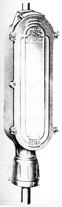
Z 1820/30 Type "B" Choke |
WAX FILLED TAPPED
CHOKE COILS AND CONDENSERS
G.E.C. Tapped Choke Coils
|
Designed to suit OSIRA 80 and 125 watt lamps, and suitable for use with a single lamp operating on 50 cycles,
A.C. supply.
An exclusive feature of the chokes is the wax filling which results in the following operating advantages :-
- 1. Choke setting remains constant, and cannot be altered in transit or by vibration.
- 2. The whole choke is meersed in was and is therefore protected from damp, dirt or dust; further, the
insultation is preserved which results in long and reliable service.
- 3. Noisless in operation.
|
Z 1821/31 Type "H" Choke
|
|
| Choke |
Wattage |
Voltage |
Overall Length in. |
Overall Width in. |
Overall Projection in. |
Weight lb. |
Price each £ s. d. |
| Z 1820 |
80 |
200/220 |
9 |
4¼ |
4½ |
13¼ |
3 9 6 |
| Z 1821 |
80 |
230/250 |
6 |
4½ |
4½ |
8½ |
2 2 0 |
| Z 1830 |
125 |
200/220 |
9 |
5 |
5 |
18½ |
3 9 6 |
| Z 1831 |
125 |
230/250 |
6 |
4¾ |
4¾ |
11¼ |
2 2 0 |
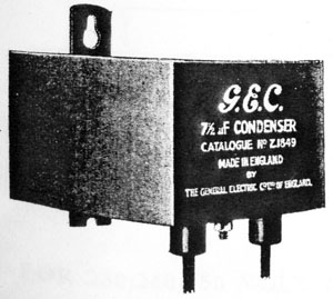
Z 1849 7½ mfd. Condenser.
|
TOTALLY ENCLOSED METAL CLAD CONDENSERS.
Condensers of the highest quality, impregnated with special high melting point compound and complete
with internal safety leak, and sealed in T.R.S. cable leads, designed, when used with a single OSIRA
low wattage lamp and choke, to raise the power factor of the unit to approximately 0.9.
| Cat No. |
Z 1849 |
Z 1850 |
Z 1881 |
| Overall Length |
4 ¼ in. |
4 ¼ in. |
4 ½ in. |
| Overall Width |
4 in. |
4 in. |
4 ½ in. |
| Overall Projection |
4 in. |
5 in. |
5 in. |
| Weight |
2¾ lbs. |
3½ lbs. |
3¾ lbs. |
|
| Cat No. |
|
Price each. |
| Z 1849 |
7½ M.F. Condenser for 230, 240/250 volt 80 watt Lamp |
16 0 |
| Z 1850 |
10 M.F. Condenser for 200/210, 220 volt 80 watt, or 230, 240/250 volt 125 watt Lamp |
18 0 |
| Z 1851 |
12½ M.F. Condenser for 200/210, 200 volt 125 watt Lamp |
1 0 0 |
TAPPED CHOKE COILS
The 80 and 125 watt OSRIA H.P.M.V. lamps are suitable for a.c. and not d.c. supplies, and must only be used
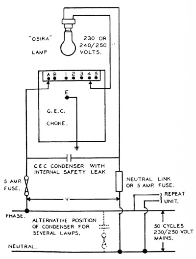
in conjunction with the special G.E.C. choke coil. The circuit must be connected in accordance with the Wiring Diagram.
The correct choke tappings should be used to suit the actual average mains voltage AVAILABLE AT THE PARTICULAR UNIT DURING
BURNING HOURS and NOT necessarily the nominal voltage of the supply system. these tappings are marked "A", "B", and
1, 2, 3, 4, 5, and are shown in the Wiring Diagram.
The chokes are accurately set at the G.E.C. Works, so that, with the correct tappings in use, the OSIRA lamps will
run at their rated wattages of 80 and 125.
If tappings intended for a higher voltage than is actually available available are used, the OSIRA lamp will
operate at low efficiency, and will be more susceptible to extinction by sudden drops in the supply voltage. It should
also be noted that in the case of Z 1820 and Z 1830 Type "B" chokes the use of the wrong tapping may
prevent the lamp starting up.
When tappings intended for a lower voltage than is actually available are used, the OSIRA lamp wattage will be too high
and damage to the lamp may result. In such circumstances the G.E.C. can accept no responsibility for lamp failure.
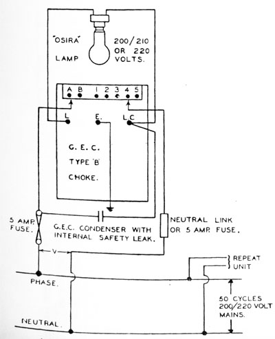
CIRCUIT
For A.C. Supplies On Voltages 200/210/220
It is essential to employ a condenser with the Z 1820 Type "B" and Z 1830 Type "B" chokes,
for use with 80 watt and 125 watt OSIRA lamps, respectively, on voltages 200/210/220. With the 80 watt it is
the Z 1850 condenser, and in the case of the 125 watt lamp, the Z 1851 lamp, the Z 1851 condenser
MUST be used. It is most important that the condenser should be connected as shown on the wiring diagram. If the condeser
is omitted, the Type "B" choke will have an excessive temperature rise. The employment of these condensers raises the power
factor from 0.45 to 0.9.
For A.C. Supplies On Voltages 230/240/250
The Z 1849 and Z 1950 condensers when used with Z 1821 "H" and Z 1831 "H" choke coils raise
the power factor from 0.45 to 0.85.
FIXING
It is most important that the G.E.C. choke coil should be mounted so that its name-plate is horizontal and uppermost.
Three fixing clips are packed with each choke coil; the triangular one being used when fixing the choke to a vertical
surface; whilst the two smaller clips should be used when fixing to a horizontal surface. (If it is desired to fit the
choke on a slopping surface, a suitable shelf or wedge must be used to bring the base horizontal.)
An indoor type conduit attachment can be supplied to cover up all the terminals and enable the leads to be run in
¾-in. E.T. conduit, it being fixed to the choke by means of the normal earth terminal E.
In street lighting units, the choke and condenser can usually be fitted (together with any fuse or switch gear) in the
base of the column. Where this is not practicable, special G.E.C. boxes to house these items can be supplied. These
boxes can be arranged with fixings either for clamping to a post or for wall mounting.
The G.E.C. choke coil is completely protected by its container, but if this is in a damp situation it should be
painted periodically.
WIRING. Important
It should be clearly understood that Z 1820 Type "B" and Z 1830 Type "B" chokes are wired differently
from Z 1821 "H" and Z 1831 "H" chokes.
FOR 200/210/220 VOLT SUPPLIES
WIRING TABLE 1
(1) Connected phase and neutral wires to Type "B" choke in accordance with the Wiring Table 1.
(2) Connect lamp leads to terminals L and LC.
(3) Connect individual condenser between LC and the fuse on the phase wire.
(4) Earth the terminal E.
|
WIRING DIAGRAM 1.
 |
|
IMPORTANT*: ON NO ACCOUNT MUST A CONDENSER LEAD BE JOINTED TO TERMINAL L, AS THIS WILL DAMAGE THE LAMP
|
WIRING TABLE 1. TAPPINGS TO USE.
Average Mains Voltage
Volts |
Connect |
| Phase To |
Neutral To |
| 185 |
B |
1 |
| 190 |
A |
1 |
| 195 |
B |
2 |
| 200 |
A |
2 |
| 205 |
B |
3 |
| 210 |
A |
3 |
| 215 |
B |
4 |
| 220 |
A |
4 |
| 225 |
H |
5 |
| 230 |
A |
5 |
|
* Wiring Table 1 shows the correct tappings and Wiring Diagram 1 the method of connections
for use with Z 1820 and Z 1830 Type "B" chokes.
FOR 230/240/250 VOLT SUPPLIES
WIRING TABLE 2
(1) Connected phase wire to A or B in accordance with the Wiring Table 1.
(2) Connect one lamp lead to terminal 1, 2, 3, 4 or 5 in accordance with Wiring Table 2 and the other lamp lead to neutral.
(3) Connect individual condenser across the fuse terminals, or group condenser across t he incoming mains.
(4) Earth the terminal E.
|
WIRING DIAGRAM 1.
 |
|
IMPORTANT*: ON NO ACCOUNT MUST A CONDENSER LEAD BE JOINTED TO TERMINAL 1, 2, 3, 4 OR 5, AS THIS WILL DAMAGE THE LAMP
|
WIRING TABLE 2. TAPPINGS TO USE.
Average Mains Voltage
Volts |
Connect |
| Phase To |
Neutral To |
| 215 |
B |
1 |
| 220 |
A |
1 |
| 225 |
B |
2 |
| 230 |
A |
2 |
| 235 |
B |
3 |
| 240 |
A |
3 |
| 245 |
B |
4 |
| 250 |
A |
4 |
| 255 |
H |
5 |
| 260 |
A |
5 |
|
* Wiring Table 2 and Wiring Diagram 2 are solely for Z 1821 "H" and Z 1831 "H" chokes.
100/150 VOLTS, 50 CYCLES
For those supplies a small step-up transformer will be needed for each unit, or a larger transformer for a group of units. Particulars
on application to the G.E.C. (Exterior Lighting Department).
SUPPLIES AT 40 AND 60 CYCLES
The standard G.E.C. chokes Z 1820, Z 1821, Z 1830 and Z 1831 are accurately adjusted to suit supplies
at 50 cycles. For any other frequency special G.E.C. chokes are necessary. Particulars on application to the G.E.C. (Exterior Lighting
Department).
GROUP SWITCHING
It is sometimes desired to control a number of OSIRA lamps with a single switch, and this is perfectly satisfactory on single-phase
supplies if the electric leads are of sufficient capacity to carry the total starting currents of the lamps without undue volt drop, and
a separate choke coil is inserted in series with each lamp.
With two-phase three-wire and three-phase four-wire systems, however, where groups of lamps are switched phase by phase, a wiring
diagram should be submitted to the G.E.C. (Exterior Lighting Department) showing proposed methods of switching, lengths and size of cables,
etc. If the phases have separate neutrals, however, no-starting troubles should be experienced.
TAPPED CHOKE COILS
| Mains voltage actual at unit. |
OSIRA lamp and choke in use. |
Installation without Condensers. |
Installation with Condensers. |
| Current and wattage at starting (excluding switching surges) |
Average running condition. |
Current and wattage at starting (excluding switching surges) |
Average running condition. |
| Amps. |
Watts. |
Current in amps. |
Power Factor. |
Amps. |
Watts. |
Current in amps. |
Power Factor. |
| 200 |
200/210v 80w. with Z 1820 Type B choke. |
- |
- |
- |
- |
0.8 |
50 |
0.55 |
0.93 |
| 210 |
- |
- |
- |
- |
0.8 |
50 |
0.50 |
0.93 |
| 220 |
220v 80w. with Z 1820 Type B choke. |
- |
- |
- |
- |
0.65 |
46 |
0.45 |
0.94* |
| 230 |
230v 80w. with Z 1821 Type B choke. |
1.35 |
40 |
0.75 |
0.50 |
0.80 |
40 |
0.45 |
0.90 |
| 240 |
240/250v 80w. with Z 1821 Type H choke. |
1.25 |
40 |
0.75 |
0.50 |
0.70 |
40 |
0.40 |
0.94 |
| 250 |
1.20 |
40 |
0.75 |
0.50 |
0.65 |
40 |
0.40 |
0.94 |
| 200 |
200/210v 125w. with Z 1830 Type B choke. |
- |
- |
- |
- |
1.1 |
60 |
0.80 |
0.89 |
| 210 |
- |
- |
- |
- |
1.05 |
60 |
0.75 |
0.88 |
* Leading power factor
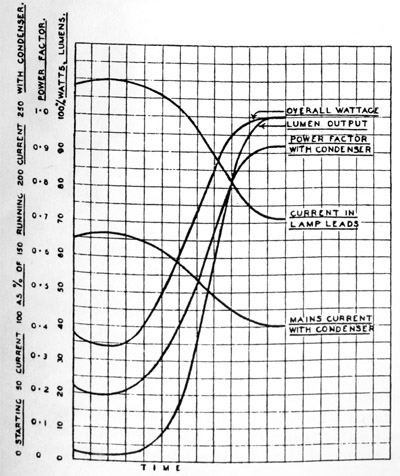
CHARACTERISTICS
The above Table shows approximate values of main current and power factor for units on 50 cycle supplies ranging from 200 to 250 volts.
(Left): Starting characteristic of a typical 125 watt H.P. Mercury Vapour Lamp.
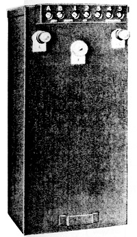
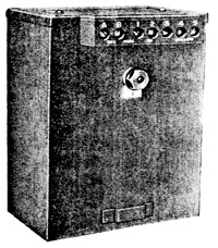
BOXES FOR 80 AND 125 WATT CHOKES AND CONDENSERS
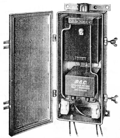
Z 1894 Box. Open and wired up.
| Z 1894 | Z 1896 |
| Overall height | 16 ins. | 19 ins. |
| Overall width | 7½ ins. | 7¾ ins. |
| Overall projection | 5½ ins. | 6½ ins. |
| Weight | 11 lbs. | 12½ lbs. |
Weatherproof Boxes for Chokes and Condensers.
Z 1894. Lead-coated sheet steel box fitted with "Parkerised" stiffening straps and higned cover with weatherproof gasket. Adequate
and weatherproof ventilation is provided ensuring a through current of air to minimise condensation. The box is suitable for housing one
Z 1821 "H" or Z 1831 "H" choke with Z 1849 or Z 1850 condenser, and fixings are provided for two ZS 2227
G.E.C. Minor Fuses. Price each £1 7 0
Z 1896. Lead-coated sheet sheel box as above; but suitable for housing one Z 1820 or Z 1830 Type "B" choke with one
Z 1850 or Z 1851 condenser and two ZS 2227 G.E.C. Minor Fuses. Price each £1 7 6
Z 1914. Post-top box for chokes and condensers.
Z 1920. Galvanised Pole Clamps for above boxes, for poles of varying diameter. Please state size when ordering. Price per set: 3s. 0d.
Z 7303. Galvanised Rag Bolts and Nuts for above boxes. Price per set: 4s. 0d.
Fuses
ZS 2227. Minor fuses (10/15 amp) Price per pair: 1s. 8d
RIMPLED OUTER GLOBES
| Depth | Diameter | Weight |
| Z 6475 | 7¾ ins. | 9½ ins. | 1¼ lbs. |
| Z 6477 | 10 ins. | 12 ins. | 2¾ lbs. |
These rimpled outer globes have been specially produced to repace the normal clear outer globes Z 6465/67 as used on the
small "Wembley" lanterns, where a rather more decorative appearance is required.
It is desired to make use of existing small "Wembley" lanterns for 80 and 125-watt OSIRA H.P. Mercury Vapour lamps, it is
essential to use rimpled outer globes. Their employment produces a slightly diffuse effect without distortion of the light
distribution, thus preventing glare, which would be present if a clear globe used.
| Price each. | | Price each. |
| Cat. No. Z 6475 | 6s. 8d | Cat. No. Z 6477 | 10s. 8d. |
The "Wembley" lanterns suitable for use with the two sizes of rimpled globes are Z 5001/16 and Z 5021/26.
In certain cases it is desirable to mount lanterns with low wattge lamps on existing street lighting columns (having a mounting height
of approximately 12 feet) without a door in the base. In such cases the Z 1914 cast-iron box with extension bracket should be
used. The box itself is 2 feet high.
|
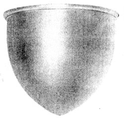
Z 6475/77
|
Z 1914
CAST IRON BOX
 Z 1914 cast-iron box for spigot mounting with a hinged cover and weatherproof gasket. Adequate ventilation is provided.
The box is suitable for housing one Z 1821 or Z 1831 "H" choke, condenser and fuses with a time switch, or one
Z 1820 or Z 1830 Type "B" choke with condenser and fuses, but no time switch. The box can be provided with an extension bracket
of lengths up to 9 feet, and a steady tube to pass inside the column. Price each £2 16s. 0d.
Z 1914 cast-iron box for spigot mounting with a hinged cover and weatherproof gasket. Adequate ventilation is provided.
The box is suitable for housing one Z 1821 or Z 1831 "H" choke, condenser and fuses with a time switch, or one
Z 1820 or Z 1830 Type "B" choke with condenser and fuses, but no time switch. The box can be provided with an extension bracket
of lengths up to 9 feet, and a steady tube to pass inside the column. Price each £2 16s. 0d.
Assembly
Several sizes of spigot caps are made for these boxes so that these items should be sent separately. After screwing the spigot cap into
the box it should be secured by means of the four-way grub screws. The lamp standard must be drilled and tapped at a distance of 18 inches
below the bottom of the spigot, so that three-way bolts can be inserted to bear on the steady tube. Long bolts with lock
nuts should be used so that, when the steady tube is held firmly, the lock nuts can be run up close to the pole, enabling the heads of
the bolts to be cut off and filed flush with the lock nuts.
Wiring
The teak board can be removed, the condenser mounted above the top fixing screw and the choke below it, leaving room for a time switch
and fuses underneath. Local inter-connection can be made and the board re-fixed to the back of the box; the two mains are then connected to
the fuses, one lamp lead to the appropriate choke tapping and the other to the neutral fuse or link.
Back to: GEC Street Lighting
|