
|
|
|
glossary
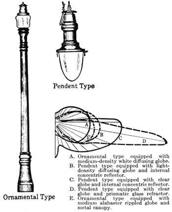
"The art of illumination although it is undoubtedly one of the most useful that has been invented by man,
and contributes perhaps more than any other to his comfort and convenience in all countries and in every class
of society, has not even been considered as an art; for the technical terms have not been invented which
are indispensably necessary in order to render it possible to treat it in a clear and satisfactory manner" - Count Rumford 1789 [Pelham 1911, vii]
glossary: standards
american candle (standard: american: obsolete)
|
|
|
See: Hefner Lamp [Pelham 1911, p9]
|
arc standard (standard: obsolete)
|
|
|
Standard proposed by screening an electric arc, originated by Methven, who screened an Argand gas flame
to give one or two candle-power. The use of an electric arc was suggested independently by
Mr. J. Swinburne and Prof. S. P. Thompson in 1892. Investigations by Pelham suggested that it would
be a poor standard due to the continuous movement of the arc. [Pelham 1911, p12]
|
bougie-decimale (standard: obsolete) (0.96-0.98 candle-power)
|
|
|
Standard proposed by the Geneva Congress of 1896. It was considered to be approximately one-twentieth of
the Violle or one-tenth of the Carcel. [Pelham 1911, p8]
|
british candle (standard: british: obsolete)
|
|
|
This spermaceti candle, six to the pound (but neither length nor diameter being specified), and intended to burn
120 grains of sperm per hour, was set up under the Metropolis Gas Act of 1860 as an official standard, for
the purpose of testing London gas. [Pelham 1911, p4]
|
candle-power (unit: obsolete)
|
|
|
Candle-power is measured as an intensity in any direction. It is also measured as a flux by the product of a
solid angle into the candle-power. (At an unofficial congress in Geneva in 1896 the name "pyr" was suggested
for a unit of intensity, and Dr. J. A. Fleming proposed the name "lamp" for a 10-candle standard - on the
ground that the candle itself having been abandoned, the name need not be retained.) - [Pelham 1911, p2]
|
carcel (standard: french: obsolete) (9.6-9.82 candle-power)
|
|
|
Earliest standard of light was the Cacel lamp, introduced in 1800, used for testing gas, and still
employed officially for that purpose in France. It is a colza oil lamp containing a clock-work pump and has an Argand burner and glass chimney of
certain specified dimensions. The value in British candle-power was determined betwen 9.6 to 9.82 - these discrepancies
may be accounted for by the many sources of error in the use of this standard. [Pelham 1911, p3]
|
english parliamentary candle (standard: obsolete)
|
|
|
See: British Candle [Pelham 1911, p4]
|
german candle (standard: german: obsolete) (1 candle-power)
|
|
|
In 1868 a carefully specified candle of paraffin was officially adopted by the German Association of Gas
and Water Engineers. It was practically the same as the British candle. [Pelham 1911, p4]
|
harcourt lamp (standard: obsolete) (10 candle-power)
|
|
|
In 1877 Mr. A Vernon Harcout described a lamp burning air saturated with the vapour of pentane. After several
modifications, it was designed to represent ten times the candle-power of the Parliamentary candle
and became the official standard of the Metropolitan Gas Referees and the unofficial 10-candle British standard. [Pelham 1911, p4]
|
hefner (standard: german: obsolete) (0.88-0.913 candle-power)
|
|
|
This amyl-acetate lamp, produced in 1884 by Hefner von Alteneck, became the official standard in Germany
after certain modifications. It was also adopted by the American Institute of Electrical Engineers,
and, provisionally, by the Bureau of Standards of the Unitied States. [Pelham 1911, p5]
|
international candle (standard: obsolete) (xx candle-power)
|
|
|
Created by the realisation that the Pentane candle, the bougie-decimale and the American candle (based on
the Hefner) were the same and therefore called the International Candle. [Pelham 1911, p9]
|
pentane lamp (standard: obsolete)
|
|
|
See: Harcourt Lamp [Pelham 1911, p4]
|
radiation standard (standard: obsolete)
|
|
|
Proposed by Lummer and Kurlbaum in Germany and Petavel in England, this uses the light emitted by one square
centimeter of the surface of platinum when raised to such a temperature that 10% of the radiation passes
through two centimeters of water in a glass cell. Considered too difficult and too expensive. [Pelham 1911, p4]
|
violle (standard: obsolete) (20 candle-power)
|
|
|
Developed by Violle and proposed for international adoption by the French at the Electrical Congress at
Paris in 1881, the standard is the light emitted in the normal direction by one square centimeter of the
surface of molten platinum. The cost of the apparatus proved prohibitive. [Pelham 1911, p7]
|
glossary: lighting
besa
|
|
|
The British Electrical Standards Association. The forerunner of the BSI.
|
brightness
|
|
|
Brightenss may be of three kinds:
- The brightness of a transparent luminous body such as a flame. (An example: a screen of 0.233 square inch in area gives a standard of 2 candle-power. Therefore the brightness of this part of the flame was 8.6 candle-power per square inch.)
- The brightness of a solid luminous body such a piece of incandescent metal or carbon.
- The brightness of a matt or rough body which reflects light in all directions.
[Pelham 1911, p23]
|
carcel-metre
|
|
|
French equivalent of the foot-candle. [Pelham 1911, p16]
|
cosine law
|
|
|
The foot-candle assumes that the illuminated surface directly faces the source of light. If the
surface is inclined to the direction of the rays of light, the illumination will diminish in proportion as
the projected area of the surface diminishes when viewed from the source of light. The visible surface
varies from unity, as seen full, to nothing when seen on edge. [Pelham 1911, p19]
|
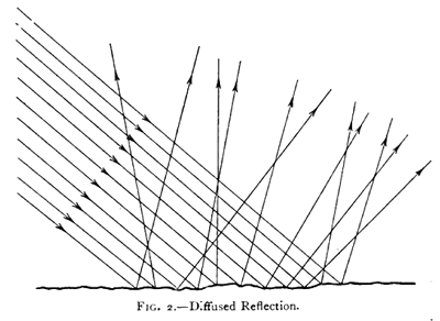
diffused reflection
|
|
|
When a beam of light falls on a rough unpolished surface the reflected light leaves it in all directions
and the quantity of light is greatest in the direction normal to the surface. In other directions it
is approximately proportional to the cosine of the angle with the perpendicular. - [Pelham 1911, p24]
|
foot-candle
|
|
|
Illumination consists of two factors, candle-power and distance. The illumination produced by
one candle-power at a distance of 1-foot was the unit recognised in England and America as the
candle-foot, first used by Sugg in 1865. However, the American term, foot-candle
became preferred. [Pelham 1911, p15]
(All these versions are unfortunate, because unlike other compound units, the quantity is not the product of
candle-power into length, but it is the quotient and the divisor is the square of the length).
The illumination of one candle at one foot is equivalent to four candles at two feet and nine candles
at three feet.
The foot-candle is a very convenient and comfortable illumination. It is for most people a sufficient
illumination for reading, and is to be found on most well-lighted dining-room tables and billiard tables. [Pelham 1911, p16]
Pelham jokes that the correct unit should be candle-toof-toof.
|
illumination
|
|
|
When light falls on a surface, that surface is said to be illuminated. The illumination
depends simply on the quantity of the light falling upon a given surface, and has nothing to do
with the colour or reflecting power of the surface. [Pelham 1911, p15]
|
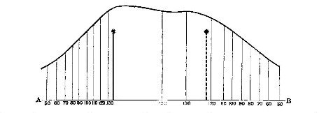
illumination curve
|
|
|
Plot of illumination at various distances along a straight line.
|
iso-lux diagram
|
|
|
Graphical representation of illumination shown in plan. The lines or contours are of equal
illumination.
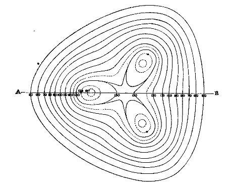
The diagram may be considered similar to the contours on a map and therefore the diagram
represents a solid. A section taken through an iso-lux diagram gives the
illumination curve for that section. (See Illumination Curve for
the curve constructed for the section AB).
"It is not suggested that the construction of these contour lines should often be carried
out, and no great importance is attached to them. The study of a few typical cases is interesting." - [Pelham 1911, p52]
|
lambert's cosine law
|
|
|
See: cosine law
|
law of inverse squares
|
|
|
The illumination of a point is calculated as the original intensity of the light divided by the square
of the distance.
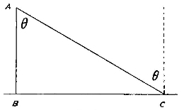
The following formulae give the illumination at 'C' from a lamp mounted at 'A'. It combines both this law and
the cosine law:
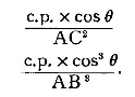
(The first formula requires the length 'AC' to be known whilst the second is derived from the first and
simply requires the height ('AB') and angle to be known and has better real-world application).
The curve of cos3θ is given below (assuming height of unity):
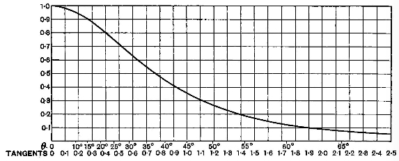
Illumination on a horizontal plane decreases so rapidly with the distance that at an angle of incidence of about
37°, or at a horizontal distance of three-quarters the height of the lamp from the ground, it falls off to
one-half; at about 45° to one-third; and at 62° or at a horizontal distance or nearly twice the height of
the lamp above the ground, one-tenth of the maximum. [Pelham 1911, p29]
This all assumes uniform illumination from the lamp source. Notable differences:
- An arc lamp gives little illumination between 0°-55° due to the obstruction of the lower carbon. The projected
area of the tip of the upper carbon varies as the cosine of the angle; therefore cos4θ is
used. [Pelham 1911, p33]
- A metal filament electric glow lamp has one or more vertical filaments. This creates a distribution related to the
sine of the angle of incidence; therefore cos3θsinθ is used. [Pelham 1911, p34]
Varying the height of the lamp results in the following curve (which follows cos2θsinθ):
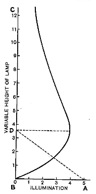
The maximum illumination occurs at height D, and it may be shown that BA = BD x √ 2
and the angle of incidence BDA is 54°44'. It will be observed that a small change in the height BD (at this height) may
be made wihtout appreciably altering the illumination at A.
Raising the lamp √ 2 dimishes the maximum illumination to
one-half, and lowering it to 1/√ 2 doubles the original
maximum. [Pelham 1911, p37]
The lamp can also be moved through a locus to provide the same minimum illumination at various distances and mounting heights
(with variations of the maximum illumination):
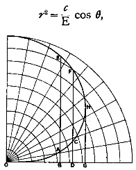
The formula gives the curve where c is the candle-power and
E is the illumination. For example, if a lamp at A on a post having a height AB
gives a certain illumination at the point O, the same lamp moved to C on the post
CD will give the same illumination at O.
Near the point H the height may be altered considerably without altering the illumination at O
materially.
OG is √ 2 times GH.
This shows that with a given candle-power and given minimum illumination on the ground, the lamps may be spaced
at a distance apart not greater than OG x 2. It is for the engineer to consider in any particular case whether
the expense of so tall a post as H is warrented, or whether a larger number of posts of height DC
would be less expensive. [Pelham 1911, p43]
|
lumen
|
|
|
Suggested by Blondel as the quantity 4π multiplied by the luminous
intensity or candle-power. Considered to be a measurement of the flux of light
or the total light. [Pelham 1911, p23]
|
lux
|
|
|
Name suggested by Sir William Preece for the standard measurement of illumination in
1889 to avoid confusion over the term foot-candle (as it gets over the difficulty of the compound
word). The name wasn't adopted then, but was subsequently used
for the bougie-meter (illumination produced by a bougie-decimale at a distance of a meter)
at the Geneva Congress of 1896. [Pelham 1911, p17]
|
mercury vapour lamp
|
|
|
The first commerically introduced lamps in 1933 were rated at 250 and 400W. The discharge takes place in a hard-glass
tube.
"Colour Modified" 400W mercury discharge lamps are introduced in 1934. These have mercury, cadmium and zinc added
to the discharge tube; the cadmium and zinc introduce blue and red light into the visible spectrum. It has an
initial efficiency of 37 lumens per watt. - [Aldington, 1936]
The metrics as given in 1936 are:
| 150 |
4800 |
32 |
1500 |
| 250 |
9000 |
54 |
1500 |
| 400 |
18000 |
61 |
1500 |
| 500 (dual lamp) |
12500 |
25 |
1500 |
([Jones, 1936])
The lamp is refered to as the High Pressure Mercury Lamp where the mercury vapour develops a pressure
greater than one-half atmosphere when the lamp is in operation. It is realised by 1936 that this is limited,
as lamps employing mercury vapour pressures of 100 atmospheres or more have been developed. In general, where the
mercury vapour pressure exceeds about 30 atmospheres, the lamps are artificially cooled and are referred to as
Super High Pressure Lamps. - [Aldington, 1936]
A 150W version was made commerically available in 1936. - [Aldington, 1936]
Lamps designed for a given mains voltage have the same arc voltage while the current is controlled to give the designated
watts. Therefore the lamp current of a 150-watt lamp will only be 3/8 of the current of a 400-watt lamp - this has an
influence on the initial efficiency. - [Aldington, 1936]
Account must be given of the temperature at which it is allowable to operate the hard glass tube in which the
arc takes place. Too low a temperature on the surface of this tube tends to produce an unstable characteristic;
too high a temperature may seriously affect the performance of the lamp during life. - [Aldington, 1936]
The relation of the wattage of a discharge tube to its volume determines the temperature at which the walls of the
discharge tube operate. The loading of discharge lamps may, teherefore, be described in terms of watts dissipation
per unit volumne of the tube. It has been found that with the types of glass [in use] a loading of some 3.0 watts per
cubic centimetre gives high value of efficiency maintenance through life. - [Aldington, 1936]
Quartz allows higher temperatures to be otained without the risk of fracture, it is more resistant to attack of metal
vapours at high temperatures and is less liable to electrolytic decomposition under higher pressures. - [Aldington, 1936]
Therefore the dimensions of the discharge tubes for a given wattage are reduced to the lowest possible value consistent
with the quartz tube operating at a temperature not greater than 1000°C. The effect is to increase the loading to
60 watts per cubic centimetre which increases the initial efficiency to 40-50 lumens per watt for 100W - 150W tubes. - [Aldington, 1936]
The increased pressure of a quartz lamp uses an incrased in the volt drop per unit length of the arc column, a
decrease in the width of the arc column, spectral broadening, and an increase in the emission of radiation at
ultra-violet wavelengths. A significant amount of the ultra-violet is transmitted through the quartz. - [Aldington, 1936]
Rhodamine has been used to improve the colour spectrum of quartz lamps. However it absorbs yellow-green light and emits as orange-red;
this reduces the overall efficiency of the lamp. Rhodamine is also slowly decomposed under the action of ultra-violet
radiation so its efficient life is relatively short. - [Aldington, 1936]
Experiments are ongoing with Barium Sulphide, Cadmium Zinc Sulphide with quartz lamps which will convert the near ultra-violet
radiation intro orange or red light. - [Aldington, 1936]
The "Dual Lamp", developed at the Siemens Lamp Works, Preston, combines a mercury discharge lamp and
incandescent lamp to reduce colour distortion. It does not require a choke or auxiliary gear. When the lamp is first switched
into circuit, the filament dissipates most of the energy, but after about 10 minutes when the
discharge tube has reached its designed voltage the thermal switch inside the lamp closes and shorts out
a portion of the tungsten filament equivalent to the arc tube voltage. - [Aldington, 1936]
Experiments are also ongoing with combinations of quartz lamps and incandescent lamps. This is proving fruitful with
the short run-up time of the quartz lamp (so the filament is only overloaded for a short time), and the mutual
temperature gain of the incandescent filament and the mercury discharge tube. - [Aldington, 1936]
|
mean spherical candle power (mscp)
|
|
|
Average of the candle-power measured in the direction of many points
uniformally distributed over an imaginary sphere around a source of light. It was considered better
than the old method (as used in the 1880s) of giving the maximum candle-power. [Pelham 1911, p20]
|
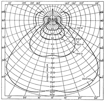
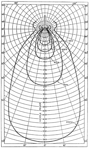
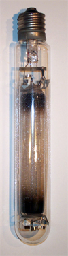
sodium discharge lamp
|
|
|
The Low Pressure Sodium.
The metrics as given in 1936 are:
| 50 |
2550 |
51 |
2500 |
| 70 |
3780 |
54 |
2500 |
| 100 |
6100 |
61 |
2500 |
| 150 |
9600 |
64 |
2500 |
(W. J. Jones, Electric Street Lighting Progress, APLE, September 9th 1936)
|
glossary: street lighting definitions
beacon lighting
|
|
|
Street lighting carried out by widely spaced lamps of such candle-power that the illumination on the
ground is less than one-hundredth of a foot-candle may be called beacon lighting. The chief use of the lamps
is to mark out the roads, and only a small area near each lamp can be said to be illuminated. In such a street, one can see carriages as
dark masses of shadow rather than illuminated objects. On a wet night one can see them better because the black masses show up against
the reflecting puddles. [Pelham 1911, p41]
(This is when the distance is more than ten times the height of the lamp , and it is useless to consider the minimum illumination
on the ground either by calculation or by measurement). [Pelham 1911, p41]
|
carriageway
|
|
|
The term carriageway in this specification denotes that part of the road specially assigned
for the use of animal or mechanical transport. [BS 307, 1931]
|
diversity factor #1
|
|
|
The ratio of maximum illumination to minimum illumination, expressed as a ratio, when appraising
schemes conforming to the British Standard 307.
|
diversity factor #2
|
|
|
The easy gradation from the standard of lighting adopted for traffic routes to that obtaining in
side streets, and at the junction between lighted and unlighted portions of traffic routes. This can be
achieved by either gradually increasing the distance of the lamps or the power of the lamps. [Davey and McGibbon, 1936, p4]
|
footway
|
|
|
The term footway in this specification denotes those portions of the highway between the
carriageway and the boundaries, specially assigned for the use of pedestrians. [BS 307, 1931]
|
highway
|
|
|
The term highway in this specification denotes the whole width of a street or road between the
fences or boundaries of land used by public traffic. [BS 307, 1931]
|
illumination
|
|
|
The illumination in foot-candles or in lumens per
square foot of a surface situated at the ground level and parallel with the plane of the highway. Only
light received directly from the installation alone is considered, light received by reflection from buildings
and the like or that received from light sources not forming part of the installation being disregarded. [BS 307, 1927]
The term illumination in this specification denotes the illumination in foot-candles or in lumens
per square foot of a surface situated at the ground level and parallel with the plane of the highway.
Only light received directly from the installation is considered,light received by reflection from buildings and the like or that
received from light sources not forming part of the installation being excluded. [BS 307, 1931]
|
illumination at a test point
|
|
|
The term illumination at a test-point in this specification denotes the illumination at one
particular test-point. [BS 307, 1931]
|
kerb
|
|
|
The term kerb in this specification denotes that portion of the highway composed of stone or
other hard materials, bordering a raised footway, margin or verge and separating it from the
carriageway. [BS 307, 1931]
|
margin / verge
|
|
|
The terms margin and/or verge in this specification denote those parts of the highway between the
carriageway and the boundaries, not specially assigned for the use of pedestrians. [BS 307, 1931]
|
mean test point
|
|
|
This denotes the mean of the illuminations at the test-points in one class of
installation or agreed section thereof. [BS 307, 1927]
The term mean test-point illumination in this specification denotes the mean of the illuminations
at the test-points in one class of installation or agreed section thereof, but
in every case it must be specified whether it refers to the carriageway or the footway. [BS 307, 1931]
|
rated illumination
|
|
|
The illumination which would be produced
if all the factors which govern the illumination were at their rated value. (This suggests the initial
illumination when the installation is new). [BS 307, 1927]
The rated illumination is the illumination which would be produced if all the factors which govern
the illumination were at their rated value. [BS 307, 1931]
|
service illumination
|
|
|
The service illumination is the illumination which prevails at a
time during the operation of an installation. (This suggests the illumination when the installation
has been running for an unspecified duration). [BS 307, 1927]
The difference between the values of the rated and the service
mean test-point illuminations is necessary in order to allow for the unavoidable
variations in the spacing and to provide for decrease of the candlepower
of the light sources, variation due to replacements or incorrect
adjustment of the light source in the fittings, soiling of glass and reflecting
surfaces of the fittings, changes in voltage or gas pressure and other
factors which may cause the service illumination to fall below the rated
illumination.. [BS 307, 1927]
The service illumination is the illumination at any time during the operation of an installation. [BS 307, 1931]
|
spacing-height ratio
|
|
|
The spacing-height ratio is the ratio of the distance between two
adjacent light sources to the height of the light source from the ground
immediately beneath it. [BS 307, 1927]
The spacing-height ratio is the ratio of the distance between
two adjacent light sources, measured along the centre-line of the
roadway, to the height of the light source from the ground
immediately beneath it. [BS 307, 1931]
|
test point
|
|
|
This denotes that point on the ground within the area to be illuminated which is equidistant and as
far as possible from the light sources which form one complete unit of the system. The illumination at
the test-point is approximately the minimum. [BS 307, 1927]
The term test-point in this specification denotes that point on the ground to be illuminated which is
equidistant and as far as possible from the light sources which form one complete unit of the system.
The test-points will be either on the carriageway or at the edge of the carriageway,
and on the road margin or on the footway. The illumination at the test-point in the carriageway
is generally the minimum for the carriageway and that at the test-point on the road-margin or footway is generally
the minimum for the whole highway. [BS 307, 1931]
|
unit of the system
|
|
|
The term unit of the system in this specification, when a streetlighting
system is regarded as a series of sources forming a repeat pattern,
denotes a single unit of the repeat pattern.
The light sources forming the unit of the system for typical installations
are shown below. [BS 307, 1927]
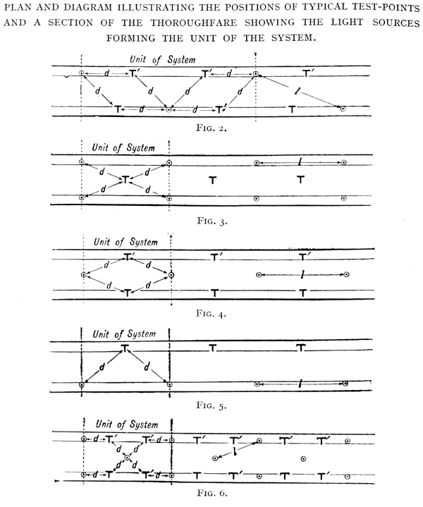
The term unit of the system in this specification denotes a single unit of the repeat pattern.
A highway lighting system is regarded as a series of sources forming a repeat pattern. [BS 307, 1931]
|
At the moment, this section is very incomplete. In time, I'll add to it - just think of it as private notes that
I've made public.
aei : associated electrical industries
|
|
|
Manufacturing company. See AEI.
|
aple : association of public lighting engineers
|
|
|
Founded in 1924, a body of professionals interested in all manner of public lighting. Their quarterly
publication, originally Public Lighing And The Public Lighting Engineer, was founded in 1936. A conference was
usually held once per year, where manufacturers were invited to exhibit their latest lamps and lighting equipment.
The organisation is now called the ILP (Institution Of Lighting Professionals) and they publish the Lighting Journal six times a year.
|
arc lamp
|
|
|
- Open-Arc Lamp (also Standard Arc or 2,000 Candlepower Lamp)
- Earliest practical form of arc lamp. For use on direct current with carbon electrodes exposed to the atmosphere. The carbons
required renewing once a day. The positive carbon forms a crater and is consumed at twice the rate of the negative carbon which
becomes pointed. 80%-85% of the total light emitted from the lamp comes from the vapourisation of the carbon at the positive electrode.
Feeding of the carbons achieved by an arrangement of solenoids acting against gravity or springs.
- A 500W, 9.6A carbon lamp furnished a maximum intensity of about 1200 candlepower. However the light distribution was unsuitable
for street lighting: maximum candlepower was downward at an angle of 45° creating a bright ring of light on the street surface near the lamp.
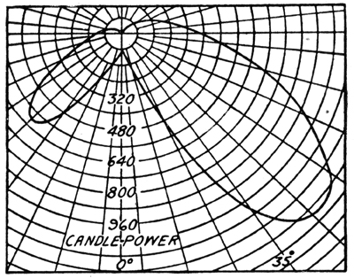
- (Note: the polar curve is unsymmetrical. It is caused by the arc wandering from one point of the periphery of the carbon to another. Therefore the
values for the polar curve were taken when the arc happened to be on the right side of the electrodes).
- The recognized illumination rating for the open-arc carbon lamp has always been 2,000 candlepower. This is incorrect, and probably due to
early photometers being unable to measure such quantities. The courts of law have decided that the 2,000 candlepower lamp describes a
particular type of lamp and has nothing to do with the actual intensity obtainable from it.
Obsoleted by the Enclosed-Arc Lamp.
- Half-Arc Lamp
- An Open-Arc Lamp but operated at 6.6A on 50V.
- Enclosed-Arc Lamp
- The arc is surrounded by an inner or enclosing globe which renders it airtight. Under these circumstances, the carbons are not consumed as rapidly and
will burn for 80 to 100 hours without trimming.
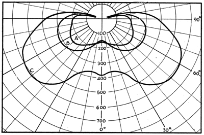
Distribution curves for enclosed carbon-arc lamps with reflectors
A - 6.6-amp, A.C. arc
B - 7.5-amp, A.C. arc
C - 6.6-amp, D.C. arc
- D.C. enclosed arc gives a natural downward distribution of light due to the existence of a crater in the upper, positive electrode. A.C.
enclosed arc gives approximately the same amount of light in the upper and lower hemispheres, and it is usually the practice to equip it
with a flat reflector. The greater steadiness of the enclosed lamp and that a relatively greater proportion of flux emitted at angles
near the horizontal gave it an advantage for street lighting.
- Flaming-Arc Lamp (Open)
- Uses carbon electrodes, either impregnated with certain salts which give luminosity to the arc, or with cores which contain the
required material. The additives were called the "flaming materials". Carbon life length was typically 12 hours. Commonly rated at
3,000 mean horizontal candlepower.
- The Bremer flaming-arc lamp was introduced in 1899. The electrodes are mounted at an angle, their tips projecting into an "economizer" which
limits the air supply to the arc and increases the life of the electrodes, and acts as a reflector. An electromagnet is used to blow and spread the arc downwards to
prevent damage to the economizer by the arc.
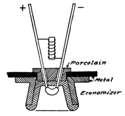
- Electrodes mounted at a downward angle to prevent slag build-up of additives; and also ensures most light is directed downwards.
- Typical early additives included compounds of calcium (yellow), strontium (red-pink), magnesium and boric acid (white).
- Because of the frequent trimming required, the flaming arc in original form was considered unsuited to American street lighting practice, so the
enclosed flaming arc was developed.
- Flaming-Arc Lamp (Closed)
- As above and developed to increase the life of the carbons. Electrodes are again mounted one above the other. Designed for 10A A.C. at
the electrodes; many contain autotransformers so can be supplied from 6.6A circuits.
- Enclosing the arc increases the life of the electrodes to approximately 100 hours, but reduces the candlepower of the lamp. Due to poor
candlepower maintenance (by deposit of ash on the globes) and because of unsteadiness of light, the enclosed flaming-arc lamp was
superceeded for street lighting.
- Magnetite-Arc Lamp (also Luminous Arc)
- Arc lamp with metallic electrodes: copper for the upper electrode and a magnetite stick for the lower. It has a high efficiency, white colour and
good candlepower maintenance. Electrode life from 100 to 350 hours (depending on amperage of lamp and length of arc). Must be used with D.C., so usually
supplied from mercury-arc rectifier sets.
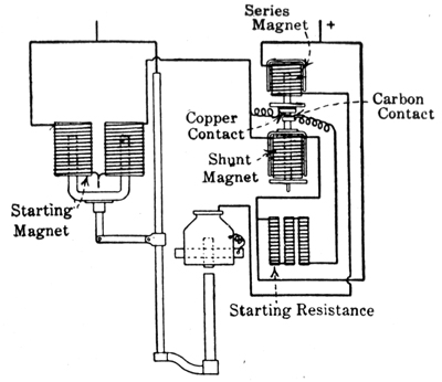
Diagram of connections for luminous-arc lamp.
- The magnetite arc met with much favour in both utilitarian and ornamental street lighting in the USA, with the ornamental 6.6A magnetite arc being most
common.
Typical distribution curves of luminous-arc lamps with different equipment.
|
ballast : control gear
|
|
|
Stabilising electronic component which regulates the current supply to a discharge lamp. As a
discharge lamp warms up, the resistance falls causing a corresponding increase in current. Without
ballast, an unchecked rising current will eventually blow a fuse or cause the bulb to fail.
The electromagnetic ballast is a simple series inductor or "choke" which limits the lamp current. This inductor
has significiant resistive and inductive losses which increase with the age of the ballast. For a 150W ballast these
losses might amount to 15%.
The inductance of an electromagnetic ballast results in a low power factor for the combined lamp-choke which can be partically
compensated by the use of a capactor across the mains.
|
bc : bayonet cap
|
|
|
Bulbholder where the bulb is inserted by pushing the base against two spring mounted electrodes and then twisting to secure.
|
bonnet
|
|
|
An older term for 'cover'. Probably named after the hat. It's use is ambigious amongst
manufacturers and this probably lead to its use become depreciated. For example,
Wardle used it to describe the canopy of a lantern
(e.g. it covers the top of the lantern) whilst BLEECO used it to
describe a Spigot Cap (e.g. it covers the top of a column).
|
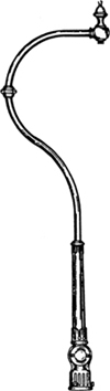
bracket : street light
|
|
Brackets are used to position the lantern in the desired place, usually above the centre of a road or above the kerb.
They're normally attached to the top of a column, but brackets are also used to position lanterns away from walls and telegraph poles.
The vast majority of brackets have one arm which supports one lantern. Other examples can have two, three or four arms to support
multiple lanterns.
Brackets are often made from the same material as their assoicated column (tubular steel, concrete), although
some manufacturers offered metal brackets for concrete columns.
Early examples are highly decorative with scrollwork and finials. By the 1950s, the designs became more austere and
functional.
With many early lanterns requiring fixing via the top of their canopy, many brackets are bent and angled. The most familar shape
is the swan neck (see left).
A bracket isn't normally required for post-top lanterns. These attach directly to the column.
|
brightness or intrinsic brilliancy
|
|
|
This is usually defined as candle power per sq. in. of projected area.
|
bs : british standards
|
|
|
The British Standards for lighting are sets of rules and regulations drawn up by the MOT and other government bodies.
They are often revised and updated. The current standards (2013) are:
BS 5489 Part 1: Lighting of roads and public amenity areas.
BS 5489 Part 2: Tunnels.
BS EN 13201 Part 2: Performance requirements.
BS EN 13201 Part 3: Calculation of performance.
BS EN 13201 Part 4: Methods of measuring lighting performance
BS EN 13201 Part 1 will no longer appear as a standard, and will probably appear as a guideline document.
Previous standards were:
- BS 307/1931: Street Lighting. Published in 1927.
It specified a test point and minimum illumination values (as foot candle classes):
|
| A | 2.0 foot candles | 30 feet | 90 feet | 3 |
| B | 1.0 foot candles | 25 feet | 100 feet | 4 |
| C | 0.5 foot candles | 21 feet | 105 feet | 5 |
| D | 0.2 foot candles | 18 feet | 108 feet | 6 |
| E | 0.1 foot candles | 15 feet | 105 feet | 7 |
| F | 0.05 foot candles | 13 feet | 104 feet | 8 |
| G | 0.02 foot candles | 13 feet | 130 feet | 10 |
| H | 0.01 foot candles | 13 feet | 130 feet | 10 |
It allowed a simple way to order and check the work of contractors and give general guidance in the planning of new work.
- BS 398/1930: ???. Publication date: 1930
This documented specified the symmetrical light distribution from light fittings. Street lighting was part of the
"Direct" class, and not less than 90% of the flux was in the lower hemisphere. The polar curves were divided into
five classes:-
- 1. Extra Narrow
- 2. Narrow
- 3. Intermediate
- 4. Wide
- 5. Extra Wide
By the 1930s it was realised that both these reports were unsuitable, and had lead to some very highly
directional reflectors and refractors giving narrow beams of high intensity, leading to glare and streakiness on the road.
They set a fashion for high peak intensity.
They were quickly succeeded by the MOT report in 1937 and subsequently obsoleted.
- BS 1308: Reinforced Concrete Street Lighting Columns. Published in 1946.
- BS 1249: Cast Iron Street Lighting Columns. Published in 1951.
- BS 1788: Street Lighting Lanterns. Published in 1951.
This document covered the mechanical and constructional features of lanterns, with regard to safety,
durability and easy of maintainance.
It did not cover photometric requirements.
- BS Code Of Practise (BSCP) 1004 Part One: Street Lighting - Traffic Routes. Published in 1952.
This refined the MOT Report of 1937 on Group 'A' roads and was supplimented by BS 1788 which was published the previous year.
The total downward light the now the most important.
- BS 1840: Tubular Steel Columns for Street Lighting. Published in 1952.
- BS Code Of Practise (BSCP) 1004 Part Two: Street Lighting - Roads other than Traffic Routes. Published in 1956.
- BS 1788: Street Lighting Lanterns. Revised in 1964.
- BS 4533: Light Fittings. Published in 1976.
|
bth : british thomson-houston
|
|
Originally a UK branch of the US Thomson-Houston manufacturing company, BTH produced a wide range of lamps and lanterns
(under the Madza tradename). BTH's range was ahead of its time, producing designs and utilizing materials which would not become
mainstream until years later.
Left: The BTH Urban Enclosed (SM278) - available as both side and top entry.
|
cdm-tt : light source : ceramic metal halide outdoor.
|
|
|
Metal halide lamp utilising a ceramic arc tube housed in a tubular outer bulb with ES cap. It was
designed to directly retrofit on HPS installations, and was also compatible with MBF/U (but this required a gear change).
Its colour was described as "warm white" and was intended for outdoors use in closed luminaries.
Ceramic arc tubes were preferred over quartz (as used for high pressure sodium discharge lamps) as ceramic arc tubes were more resistant
to attack by the metal halide salts within the tube.
The lamp was not recommended for dimming.
It was superseded by the CDO-TT range (which could be dimmed).
The lamp was manufactured by Philips as the MASTER City White and was available in 70W and 150W sizes. The 'CDM'
was a Philips code, presumed to stand for 'Ceramic Discharge Metal halide'. The 'TT' was another Philips code representing
the ES lampholder.
| 70 |
6300 |
E27 |
| 150 |
13500 |
E40 |
|
cdo-tt : light source : ceramic metal halide outdoor.
|
|
|
Metal halide lamp utilising a ceramic arc tube housed in a tubular outer bulb with ES cap. It was
designed to directly retrofit on HPS installations, and was also compatible with MBF/U (but this required a gear change).
Its colour was described as "warm white" and was intended for outdoors use in closed luminaries.
Ceramic arc tubes were preferred over quartz (as used for high pressure sodium discharge lamps) as ceramic arc tubes were more resistant
to attack by the metal halide salts within the tube.
The lamp could be dimmed with special operating gear.
It superseded the earlier CDM-TT range.
The lamp was manufactured by Philips as the MASTER City White and was available in 70W, 100W, 150W and 250W sizes. The 'CDO' was
a Philips code, presumed to stand for 'Ceramic Discharge Outside'. The 'TT' was another Philips code representing
the ES lampholder.
| 70 |
6300 |
E27 |
| 100 |
8800 |
E40 |
| 150 |
13500 |
E40 |
| 250 |
22500 |
E40 |
|
cfl : light source : compact fluorescent.
|
|
|
|
cmh : light source : ceramic metal halide.
|
|
|
A development of metal halide bulb technology, in which the arc tube is constructed from a ceramic compound. The
use of ceramics (over the traditional quartz) allowed increased loading of the arc tube and resisted the attack of the metal halide salts.
Although proposed as a technology in the mid 1960s, practical considerations (such as the corrosion of the metal wires passing
through the arc tube) prevented the production of lamps until 1981 when Thorn unveiled their TSH (Tin Sodium Halide) lamp.
Unfortunately the bulb required special gear so research continued throughout the 1980s but halted when
GE cancelled the project (when they purchased Thorn).
It was left to Philips to continue the project and solve the technical problems. Their CDM range was
announced in 1994.
|
candela
|
|
|
Measurement of the luminous intensity of light (introduced in 1948 by the International Committee on
Weights And Measures).
|
candle power
|
|
|
Candle power is measured simply as an intensity in any direction, and the expression signifies the unit of luminous
intensity. The term candle-power was originally derived from the luminous intensity of the candle flame, the
candle being generally supposed to yield a flame of unvarying intensity.
English Parliamentary Candle was set up about 1860 as an official standard to be used for the
purpose of testing gas. It is described as a pure spermaceti candle weighing 1/6th of a pound and
burning at a rate of 120 grains per hour. It was set up as an official standard for the purpose of gas-testing.
International Candle was adopted as the international unit of candle-power by Great Britain,
France and the United States of America. Such a candle is defined as being equal to one Pentane candle, or
1.11 Hefner units (the Hefner being the German unit and denoting a luminous intensity of the Hefner lamp
under standard conditions).
It has been superceeded by the Candela.
The candle power as a unit of light intensity originally represented the horizontal intensity
of light from the British Standard Candle, but since the value can be more accurately preserved and reproduced in the incandescent lamp.
This arbitrary value is now maintained in tested incandescent lamps in the National Physical Laboratory, and in other countries.
The unit of light in general use in Great Britain, France, United States and other countries (Germany excepted) is termed the
"International Candle."
The relations of the International Candle to other terms are as follows:-
- 1 International Candle - 1 Pentane Candle (Great Britain)
- 1 International Candle - 1 Bougle Decimale or 0.104 Carcel Units (France)
- 1 International Candle - 1.11 Hefner Units (Germany)
|
column : street light
|
|
|
A (normally) vertical pole which positions a bracket (optional) and lantern at the required height.
Traditionally columns were made from cast iron, but during the 20th century, other materials were used such
as steel, concrete, fibre glass, plastic and even wood. Steel became the most popular by the end of the
century, but concrete was extremely popular in the decades following World War II due to metal shortages and rationing.
Initially, particularly when cast from iron, columns were extremely decorative. Such embellishments gradually
disappeared and columns became simpler over the years.
Cast-iron and early concrete columns were designed to withstand vehicle collisions but such thinking
radually disappeared during the 1960s with designs which would crumple and even shear off at the base.
Some columns were designed with a door at their base for the housing of fuses, control gear and timing
mechanisms within the column. Earlier columns, such as those originally designed for gas lanterns, had
no such compartments.
|
control gear : control gear
|
|
|
The electronic components required to start and maintain an electric discharge
through a discharge lamp. The numbers and types of component depend on the type
of discharge lamp being used. Typically they include a ballast (to maintain the electric
discharge), an ignitor (to start the electric discharge) and a power-correction capacitor.
Other components, such as radio interference suppressors and magnetic arc deflectors may also be required.
See: Ballast.
|
cri : lighting term: colour rendering index.
|
|
|
Colour rendering index (Ra - general colour rendering index). An index representing the colour shift that
coloured surfaces undergo when lit by the given light source compared with the colour of the same surfaces under a reference
source of comparable colour temperature. CRI values range from 0 to 100, where 100 represents the reference source. A high
CRI does not necessarily guarantee good colour rendition, undless the reference itself renders colours well. The colour
rendering of a light source should be compared with daylight if its correlated colour temperature is >5000K and to a black
body source if it is not.
Low pressure sodium has a CRI of zero (which is why it has been excluded from current specifications).
|
cut-off: optical systems
|
|
|
Provides a rapid reduction in luminous intensity at the angle specified. In street lighting lanterns this is
typically in the region of 80° to the horizontal.
Typically in older specifications, the maximum intensity is at 70° to the downward vertical with a negligible
amount of light at 80° and above.
|
davis : manufacturer
|
|
One of ELECO's companies, DAVIS produced the popular ex-ELECO range in the late 1980s.
Left: The DAVIS GR100 - originally an ELECO design.
|
diffused reflection
|
|
|
When a beam of light falls upon a rough unpolished surface the reflection is no longer regular, but the rays are
scattered in all directions. The surface on which the light falls appears luminous, and behaves as if itself were the
source of light. No image is formed (as is the case with specular reflection).
The separate incident rays are all reflected according to the laws of reflection, but owning to the fact of the
various parts of the surface being inclined at different angles to those rays, the latter are reflected in all directions,
or a beam composed of scattered rays results.
|
DLOR: optical systems: downward light output ratio
|
|
|
Downward light output ratio. The ratio of the light emitted in the lower hemisphere to the light emitted by the lamp.
|
electronic control gear : control gear
|
|
|
Solid-state alternative to traditional inductive electromagnetic ballasts. Uses Pulse Width Modulation (fast
electronic switching) to control the lamp current by providing it with a high-frequency series of current pulses.
It also produces the initial high-voltage starting pulse and may have other control functions such as dimming and
programming.
An electronic control gear controlling a 150W lamp would typically have losses of 5%.
Reliability and length-of-life are current issues with electronic gear which are far more electronically complex
than older electromagnetic ballasts.
See also: Ballast.
|
efficacy : lighting term
|
|
|
The ratio is total light output of a lamp in Lumens to the energy input to the lamp in watts.
Measured in lumens per watt or lm/watt.
|
es : edison screw
|
|
|
Threaded bulbholder where the bulb is inserted by screwing it in.
|
eleco
|
|
This manufacturing company produced a highly popular range of lanterns, brackets and columns which were
utilised throughout the UK. They were most popular in the 1960s and 1970s and produced some of the most
striking designs from that period, whilst also producing some of the most bulbous.
Left: The Eleco Lunar (PT 1006) - an example of a striking design.
|
elma : electric lamp manufacturers' association of great britain
|
|
|
Cartel formed by the merging of the two principle lamp rings in 1919. They represented 90-95% of the market, fixing prices and
regulating output, primarily for the interests of GEC, BTH and Siemens. After
government interventions and rulings, ELMA eventually became a trade union. It's assumed that the
ring was broken by the Second World War.
|
esla : the electric street lighting apparatus co.
|
|
Manufacturing company based in Canterbury, Kent who are primarily remembered for the ultra-collectable Bi-Multi range of
lanterns.
|
finial
|
|
|
Fitting at the top of a bracket. Can be purely decorative (such as a Fleur-De-Lis at the tip
of a curved bracket) or is functional i.e. supporting a top-entry lantern.
|
flux of light
|
|
|
The flux of light is measured in lumens, and is equal to the intensity of the illumination multiplied by the
area over which it is distributed.
- M.S.C.P * 4π = Total Lumens.
- Foot Candles * sq. ft. = Lumens.
|
foot candle
|
|
|
The Foot-Candle is the illumination produced by a light flux of one lumen, uniformally distributed
over an area of one square foot.
The Foot-candle is a unit of intensity of illumination; it is defined as the illumination produced by a source
of one candle power on a surface everywhere one foot distant from the source.
Frequently, though more generally in American literature, the foot-candle is defined as an illumination of one
lumen per square foot, this definition involving a consideration of luminous flux.
Since the candle-power of a souce varies with the direction, there is much to be said for the latter method
of measurement.
|
frog
|
|
|
Spindly metal construction connecting post-top gas lanterns to columns.
|
ges : goliath edison screw
|
|
|
Threaded bulbholder where the bulb is inserted by screwing it in. These are used for larger wattage bulbs, typically 250W to 400W high
pressure mercury.
|
gls : general lighting service
|
|
|
The classification of incandescent light sources.
The first incandescent bulbs used carbon filaments in a vacuum; these were then replaced by tungsten filaments in a vaccum; to
be finally superceeded by gas filed tungsten filament bulbs. (An inert gas was pumped into the bulb to slow down the loss of
tungsten atoms from the filament).
The original bulbs used a coiled filament, whilst coiled coil tungsten filament lamps started appearing in the 1930s: these
became the standard. Old 1930s open GLS lanterns (such as ESLA Bi-Multis or
BLEECO open dome refractor lanterns) should be fitted with clear single coil bulbs.
Typical wattages are: 40W, 60W, 75W, 100W and 150W (for Group B roads); 200, 300, 500 and 1000W (for Group A roads).
Variations of the GLS source are:
Clear Lamps: These are clear glass bulbs.
Pearl Lamps: Are the most common types of incandescent lamp. These are internally etched to produce a
diffusing finish and usually have a grey unlit appearance.
Opal Lamps: Are less common, being sprayed inside with a diffusing coating.
They have a white unlit appearance (similar to a coated elliptical MBF or SON).
|
glare
|
|
|
An effect of light which is so much brighter than the current adaptation level that either visual
impairment or discomfort is caused.
In the 1930s, it was believed this was governed by three factors:
- The brightness of the lamps.
- Position relative to the observer.
- A factor which takes account of the relative movement of observer and lamp.
Directing light at one degree below the horizontal was seen to be adventageous in the 1930s, but a cause of
glare. Some authors suggested ways to minimalise it, even suggesting graduated filters along the top of
car windscreens.
|
glare (disability)
|
|
|
Glare that impairs the vision of objects, caused by light scattering within the eye.
|
glare (discomfort)
|
|
|
Glare which causes discomfort without necessarily imparing the vision of objects. The degree of
discomfort depends on the intensity of the light source, its position in the field of view,
and on the background luminance.
|
gs
|
|
|
Gas Filled. A term from the 1930s to describe the new gas filled tungsten filament lamps. Before then, the filament
was held in a vacuum. Keeping the filament in an inert gas filled environment slowed the evaporation of tungsten
from the white hot filament.
This became the standard.
|
globe
|
|
|
Glass bowl enclosing a lamp. An early term for bowl. Used to protect
the lamps, and provide an early form of light control (either through reflection from the
upper part of the globe and/or diffusion from its opaled surface).
When bowl became the preferred term, globe was used to describe spherical, decorative
glass or plastic bowls for street lights.
|
hid: high intensity discharge
|
|
|
A class of lamps in which an arc is struck between electrodes in a small quartz or
polycrystalline alumina (ceramic) arc tube. This contains a metallic dose and a starting
gas at relatively high pressure compared with low-pressure lamps. The metallic dose vapourises
as the lamp warms up.
|
hps: high pressure sodium
|
|
|
|
ignitor: control gear
|
|
|
Ignitors provide a brief, high voltage pulse or pulse train to ionise the gas between the
electrodes of a high-pressure discharge lamp.
|
illuminance: lighting
|
|
|
Density of luminous flux falling on a surface. The measurement unit is the Lux (Lumens/m2) - symbol Lx.
There are other categories depending on the shape of the surface:
- Hemispherical: Luminous flux on a small hemisphere with a horizontal base, divided by the surface area of the hemisphere.
- Horizontal: Illuminance on a horizontal plane.
- Semi-Cylindrical: Total luminous flux falling on a curved surace of a very small semi-cylinder divided by the curved surface area of the semi-cylinder.
- Vertical: Illuminance on a vertical plane.
|
illumination
|
|
|
The unit of illumination is the Foot Candle.
|
inequality ratio
|
|
|
The inequality ratio is the ratio between the maximum illumination and minimum illumation of a road surface. It is calculated
as maximum illumation / minimum illumination.
|
initial light output of lamp
|
|
|
The light output after 100 hours burning from new.
|
intrinsic brilliancy
|
|
|
The intrinsic brilliancy of a light source is generally expressed as the candle-power
per square-inch of surface exposed in a given direction.
|
lamp lumen maintenance factor
|
|
|
The proportion of the initial light output which remains after a given time as a result of
lumen depreciation.
|
lamp life
|
|
|
The operating time after which a stated proportion of the lamps have failed. Lamp life is normally
distributed. Manufacturers often quote life to 50% failure.
|
lantern : street light
|
|
|
Assembly to redirect light as desired and to protect the light source. Optionally lanterns could also house
any necessary control gear and lighting control mechanisms e.g. a photo-cell.
The term "lantern" is now superceeded by "luminaire".
|
lantern body
|
|
|
The body of the lantern can be made in the following ways:
- Spinning
- Steel
- Copper
- Fabricated Box
- Casting
- Iron
- Silicon Aluminium
- Gravity Die
- Pressure Die
- Plastic Moulding
|
laws of reflection
|
|
|
The laws of reflection may be stated as follows :-
- The reflected ray lies in the same plane as the incident ray and the normal, but on the opposite side of the latter.
- The angles of incidence and reflection are equal.
|
led
|
|
|
Light emitting diode.
|
light control
|
|
|
This is the method of directing light flux from a light source in designated directions. They are:
- Absorption: Part or practically all of the light losses its identity and is converted into heat.
- Refraction: Bending of a ray of light due to its passing from one transparent medium to another of greater or less density.
- Reflection: Throwing back or redirection of rays by a surface.
- Diffusion: The breaking up of a beam and spreading of its rays in all directions by the medium through which it passes
or by the surface upon which it falls.
Various technologies,
and combinations of those technologies, are used in a lantern:
- Reflector
- Vitreous Enamel
- Glass Or Plastics
- Silvered
- Aluminised
- Prismatic
- Anodised Aluminium
- Reflector-Refractor
- Refractor
- Single Piece
- Sealed Two Piece
- Glass
- Soda-Lime
- Heat Resisting
- Plastic
- Processed Sheets
- Injection Moulding
- Diffuser
|
light source
|
|
|
The source of light from a street lighing lantern can be produced by a number of different technologies.
- Incandescent Filament (GLS)
- Discharage Lamp
- Low pressure sodium (SO/H)
- Mercury
- Discharge MA/V, MA/H, MB/U
- Blended MBT/V
- Bulb Fluorescent MBF/U
- Tubular Fluorescent MCF/U
- Gas
- Low pressure
- High pressure
- Arc Lamp
|
lighting system
|
|
|
Early classification system to categorise interior lighting systems. Whilst strictly not within the scope of street lighting,
some aspects of the BS Specification for Lighting Fittings (398/1930) for direct lighting were adopted by at least one
manufacturer for street lighting i.e. REVO.
- Direct Type Reflectors are placed above the lamp to redirect the horizontal and upward distribution onto
the working plane. (As typified by Benjamin Steel Reflectors and many Reflector Fittings.)
These have the highest efficiency, but care should be taken that glare from the exposed filaments should not occur. The shadow
effects are, however, somewhat harsh, thus rendering them unsuitable for certain purposes.
In the 1910s, three specific subcases were recognised. These cases were sometimes quoted for very early street lighting
reflectors.
- Extensive Reflectors. These give a wide distribution of light and are suitable for rooms which are
low in comparison with their width or length, or for rooms employing a single central fitting. Such reflectors provide uniform
illumination over a surface whose radius equals the height of the lamp above the working plane, from which it is clear
that if a large space is to be illuminated by several lamps, they must be fixed a distance apart equal to twice their height.
Usage: General Room illumination.
- Intensive Reflectors. These provide an intermediate illumination i.e. a uniform illumination over an area
whose radius is three-quarters the height of the lamp above the working plane, and consequently should be placed a distance
apart equal to one and a half times their height.
Usage: Desk Illumination.
- Focussing Reflectors. These throw an intense light over a small area, and are brought into use
if special illumination of any particular object is required. Such a reflector will provide a uniform illumination
over an area whose radius equals half the height of the lamp above the working plane, and lamps should be placed a distance
apart to their light.
Usage: Object Illumination.
- Concentrating Reflectors. These are required in cases that require exceptional
illumination.
- There are also Dispersive and Distributing Industrial reflectors - see APLE Conference 1932, Credenda.
Usage: Object Illumination (such as shop-window illumation.)
In 1930 (BS 398/1930), the classication of the polar curve was divided into five classes, which cast 90% of the total
flux in the lower hemisphere:
- Extra Narrow.
- Narrow.
- Intermediate.
- Wide.
- Extra Wide.
- Semi-Indirect Fittings are provided with an opalescent bowl beneath the lamp. Only a portion of the light
is transmitted directly by the bowl, the greater part being reflected on to the white celining or a top refelctor and thence
re-directed to the working plane.
Their efficiency is appreciably less than that of direct type reflectors, but they cast much softer shadows and the opalescent
bowls effectively prevent glare.
- Indirect Fittings consist of an opaque bowl, having an internal reflecting surface, suspended beneath the lamp.
Thus the whole of the light is directed to the ceiling, or to a top reflector, and thence to the working area.
They provide a light practically devoid of shadows at a still further sacrifice of efficency.
All types of lighting system have be used for street lighting, with the Direct being the most common.
Indirect Fittings always utilise a top reflector.
|
lighting types
|
|
|
The spread of light from a lantern is characterised in the following ways.
- Prestige And Display
- BS Code Of Practise
- Group A
- High Angle
- Medium Angle (including Aeroscreened)
- Cut-Off
- Uni-Directional
- Group B
- Narrow B1
- Wide B2
- Tree Lined
|
lor: light output ratio
|
|
|
Light output ratio. The ratio of the light emitted by the luminaire to the light emitted by the lamp.
|
lps: low pressure sodum
|
|
|
Low pressure sodium.
|
lumen
|
|
|
The Lumen represents the quantity of light falling on one square foot of the surface of a sphere of one
foot radius from a light source of one candle intensity; placed at the centre of the sphere.
The Lumen is the unit of light flux. It is equal to the amount of light required to produce an intensity of
one foot-candle over an area of one square foot.
|
lumen depreciation
|
|
|
Continuous loss of output throughout life common to all discharge lamps. Varies according to the
type of lamp.
|
luminaire maintenance factor
|
|
|
The ratio of the light output of a luminaire in a specified state of dirtiness to the light
output when clean.
|
luminance
|
|
|
Radiance weighted by a special function representing human visual perception of brightness.
Unit candelas per square meter - symbol Cd/m2.
|
luminous flux
|
|
|
Imagine a luminous source radiating flux with unit intensity in all directions. Such a source will be a point source
of unit intensity, or one candle-power, the intensity in all directions being the same.
From the source, unit flux will be given out within each unit solid angle, the total luminous flux being equal to
that within each unit solid angle multiplied by the number of such angles about the source.
The unit of luminous flux defined above is known as the lumen, and thus from the source the total flux
of light must equal 4π lumens.
If such a source be surrouned by a sphere of radius equal to one foot, the total flux emitted will be intercepted
by the surface of the sphere, and the flux incident upon each square foot of the surface will be given by :-
flux (4π) / area (4π) = 1 lumen per square foot.
since the flux is 4π lumens and the area 4π square feet.
According to the definition of illumination it is clear that the illumination on all points on the surface of the
sphere is the same and equal to one foot-candle, all points being the same distance - one foot- from the source of
one candle power.
|
ma : light source : mercury medium pressure.
|
|
The designation of the first commercial mercury discharge lamps. Invented by the GEC in 1932, the first installation
was erected in East Lane, Wembley in 1932. Consisting of 400W Osira lamps in clear glass globes, the second installation in the
newly designed Z8001 was installed in Wembley Way later that year.
400W bulbs were first available, quickly followed by 250W units. A 150W version was launched in 1936, but, due to the medium
pressure of the mercury vapour, suffered from efficacy problems. Therefore the race was on to develop a high pressure version
of the bulb which could operate well at lower wattages.
- The orientation of lamp burning was also important, and several designations were used:
- /V Vertical cap up
- /D Vertical cap down
- /H Horizonal
- /U Universal
Mazda (BTH) sold the lanterns under their Mercra name. The GEC could only
use the Osram name for tungsten filament lamps, so sold their mercury lanterns as Osira up until
the second world war. Philips used Philora, whilst Siemens used
Sieray.
Siemens were advertising the Sieray-Dual Lamp in 1936 as a combination of mercury discharge
lamp and tungsten filament. The light quality was considered better from this bulb, and it didn't require any gear (the
tungsten filament acting as ballast with its fixed resistance). The designation for this bulb became MAT and was also
known as Blended Mercury.
- There were a couple of variants (which extended the lamp's code):
- T With a tungsten filament. See above.
- F Coated with a fluorescent power to improve the light quality.
| 250 |
9000 |
1,500 hours |
| 400 |
18000 |
1,500 hours |
|
magnetic arc deflector : control gear
|
|
|
Electromagnet mounted above an electric arc to push the arc downwards to prevent damage.
First known use was in the Bremer flaming-arc lamp; the electromagnet is used to blow and spread the arc downwards to
prevent damage to the economizer by the arc.
Later used to allow MA/V lamps to be mounted horizontally. The small magnetic coil is positioned in a lantern above the lamp to correct the upwards
bend of the arc caused by heat convection. The magnetic field of the coil pushes the arc back into the centre
of the arc tube. Power consumption is typically 1W.
If the magentic arc deflector isn't used for a horizontally mounted MA/V bulb, the arc will rise sufficiently
to hit the arc tube and destroy the bulb.
|
mantle
|
|
|
???
|
mh: metal halide
|
|
|
Metal halide.
|
methods of control
|
|
|
This breaks down how a street light is switched on and off.
- Hand operated (both individual and group)
- Time clock operated (both individual and group)
- Centralised control using high frequency impulse or DC Bias.
- Contactors in cascade.
|
mhcp: mean horizontal candle-power
|
|
|
The Mean Horizontal Candle Power is the average power given off in the horizontal plane of a lamp through the centre of the light.
The Mean Spherical Candle Power can be averaged from the MHCP by multiplying by 0.8 to 0.85.
|
mscp: mean spherical candle-power
|
|
|
The Mean Spherical Candle Power is the average of the candle power given off in all possible directions.
(i.e., at all points of a sphere surrounding the lamp).
Imagine a luminous body to be surrounded by a sphere and a number of points uniformally distributed over the
surface of the latter to be taken.
If the candle-power be now measured in the direction of radii to each of these points, the average of all the
intensities so found is called the mean spherical candle-power of the source.
The M.S.C.P. of a metal filament lamp can be found by multiplying the Mean Horizontal Candle Power by a factor
which varies between 0.8 and 0.85.
|
mot : ministry of transport
|
|
|
The government department in the UK responsible for the transport infrastructure. They're write the guidelines and
rules governing street lighting.
They published their first report in 1937 (with an interim report in 1935 which covered main roads only) which superceeded and obsoleted the British Standards 307
report of 1927. The amount of light from a lantern was just one criterion (it was the principle subject of BS 307). Definite
spacial arrangements of lanterns in terms of height and distance were standardized, and there were limits placed on the peak intensity
of the beam, leading to improvements of glare. It was also the first document to divide roads into Group 'A' and Group 'B'.
|
mounting height
|
|
|
The Mounting Height is the vertical distance between the Working Plane and the centre of the lamp filament. For street lighting
it is taken as the vertical distance from the road surface to the centre of the lamp filament.
|
non cut-off
|
|
|
Maximum intensities are directed at angles close to the horizontal. This type of
lighting will be accompanied by a certain amount of glare. The maximum intensity is at
80 degrees ot the downward vertical, with no limitation on the amount of light at higher
angles.
|
opaque body
|
|
|
An opaque body does not allow light to pass through it at all. They are largely employed in the indirect system
of lighting, the lamps being surrounded by bowls of opaque material. Opaque surfaces are also largely employed for
general reflection purposes.
|
optical systems
|
|
|
The optical systems utilitised by street lighting lanterns include:
- Symmetrical
- Axial Asymmetric
- Non-Axial Asymmetric
- Uni-Directional
|
optikon
|
|
|
Physical embodiment of the various reflecting or refracting devices in a lantern. Therefore a lantern
consists of a canopy (or body) and an optikon. A term used by the GEC in the 1950s.
|
pecu
|
|
|
Photo-electric control unit.
|
photo cell
|
|
|
Early versions, known as Light Actuated Switch, used a selenium cell and a single valve amplifier unit.
By the 1930s, a new circuit was employed, which didn't require a valve. It was known commercially as the Radiovisor Bridge.
|
public lighting : public lighting and public lighting engineer
|
|
|
The official publication of the APLE. Founded in 1936 and published quarterly. Was renamed Lighting Journal
and is now published as just LJ.
|
radiance
|
|
|
Summation fo the power spectrum of radiated energy (in watts).
|
radio interference
|
|
|
This was found to be caused by some types of street lighting in the 1950s. The solution was to connect a 0.01 microfarad capacator (for 80W) or a 0.1 microfarad capacator (for 400W) across
the terminals of the bulb.
|
raising/lowering gear
|
|
|
Pulleys and wires allowing lanterns to be raised and lowered. Advantages and disadvantages are:
- Low labour costs for maintainance.
- Lanterns more easily cleaned on the ground.
- Maintenance can be effected without causing a traffic obstruction.
- Elimination of risk of accidents with tower wagons.
- However... installation costs more and additional equipment needs maintaining.
- Jarring and shock can cause filament or bulb failure.
|
regular reflection
|
|
|
When a beam of light falls upon a smooth, polished surface then the reflection is regular and the rays are reflected
according to the laws of reflection. An image of the source of light can be seen the same distance behind the mirror as the
luminous object is in front of it.
|
semi cut-off: optical systems
|
|
|
Provides a slow reduction in luminous intensity at the angle specified. In street lighting lanterns this is
typically in the region of 80° to the horizontal.
See also: Cut-Off.
|
sinusoidal diagram
|
|
|
Introduced in 1932 as a measure of the utilisation of a lantern. When "Iso-Candle" lines are plotted on it,
it becomes known as an "Iso-Candle Diagram."
|
so : light source : low pressure sodium, one cap.
|
|
|
Designation of the first sodium lamps, invented by Philips in 1932. The first trial installation was along
a road in Eindhoven, Holland (see below). At first the authorities were hesitant about the colour of the lamp and dared
not use it. But Dr. A. F. Philips agreed to install the trial installation, and if it wasn't pleasing,
Philips would take it down, paying all costs.
At first, there was much laughter about the "queer yellow lamps" but motorists soon realised their benefits (good visibility, less glare, better performance in fog).
Therefore the trial installation was kept.
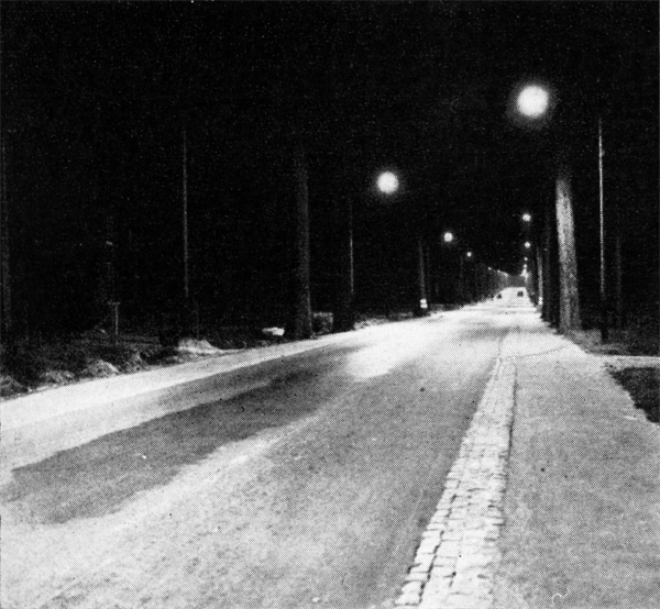
The first installation in the UK was in Purley Way,
Croydon, outside the airfield, also in 1932 (see below). This was probably prompted by the successful trial of the
GEC's MA discharge lamp in East Lane, Wembley, early in the year.
It appeared that this first installation (100W DC) was installed in bucket-type cut-off lanterns. It lasted four years
before being replaced with a larger installation of Wardle Liverpools on a catenary system,
which lasted until the 1970s.
The bulb was typified by a two piece construction - the inner arc tube was enclosed in an outer tube which comprised a
Dewar flask. When the inner tube was spent, it was removed and replaced - the outer tube, which was expensive to construct,
was retained.
The Dewar vacuum chamber provided thermal insulation, allowing the inner tube to reach its optimum temperature of 260oC.
The original wattages and efficiencies were:
| 50 |
2550 |
| 70 (later 65) |
3780 |
| 100 |
6100 |
| 150 |
9600 |
Philips sold the bulb under the Philora name - technical information can be found
here.
On the 15th Novemebr, 1938, ELMA reclassified the wattage and efficiencies as follows:
| 45 |
2500 |
55.5 |
42 |
| 60 |
3900 |
65.0 |
49 |
| 85 |
6100 |
71.5 |
57 |
| 140 |
10000 |
71.5 |
57 |
By the early 1960s, the efficiencies of the lamps had improved:
| 85 |
6200 |
5525 |
| 140 |
10250 |
9100 |
- The orientation of lamp burning was also important, and several designations were used:
- /V Vertical cap up
- /D Vertical cap down
- /H Horizonal
- /U Universal
The lamp was superceeded by the SOI design.
|
solid state energy saver
|
|
|
A low loss low pressure sodium ballast incorporating both a choke and a thyristor. These devices were
marketed by DAVIS in the late 1980s, and a data sheet can
be found here.
|
spacing ratio
|
|
|
The spacing distance divided by height. The height is taken as distance between the ground and the filament
of the lamp.
|
spacing distance
|
|
|
The spacing distance is the horizontal distance between two adjacent lamps.
|
spigot
|
|
|
The top of the column, which has a smaller radius, and allows a bracket with Spigot Cap to be fitted onto it.
|
spigot cap
|
|
|
Screwed to the base of a bracket, it allows the bracket to be secured to the top of the column by means of three or four
bolts. It fits onto the Spigot.
|
thyractor
|
|
|
A marketing name by DAVIS, the thyractor was a combination of
a low loss choke (the reactor) and a thyristor. The thyristor was used as an ignitor.
Such a device would be used for SOX, SOX Plus and SOX-E.
DAVIS also sold this device as a converter unit from MBF to
SON. Chokes can be connected in series, so the low loss choke decreased the wattage by a set amount
(from 80W for MBF to 70W for SON for instance) and the thyristor acted as an ignitor.
A data sheet for these devices can be found here
|
translucent body
|
|
|
A translucent body is one through which light can pass, but through which bodies cannot be distinctly seen.
Translucent globes are used extensively in electric lighting to prevent a direct view of a luminous filament
from being obtained.
|
transparent body
|
|
|
A transparent body is one through which objects can be distincty seen.
|
ulor: upward light output ratio
|
|
|
Upward light output ratio. The ratio of the light emitted in the upper hemisphere to the light
emitted by the lamp.
|
unit candle
|
|
|
Obsolete measurement of the intensity of light (replaced by the Candela).
|
utilisation factor
|
|
|
The percentage of light available which is incident upon the surface to be illuminated.
|
WLC: whole life cost
|
|
|
Whole life cost.
|
working plane
|
|
|
The Working Plane is the surface to be illuminated. For bench work and factory operations, it is generally taken
as a plane parallel with, and 3 feet above, the floor. For early street lighting calculations in the 1920s (using
the illumination model) it was also taken to be 3 feet above the floor i.e. the position of the driver.
|
|
|