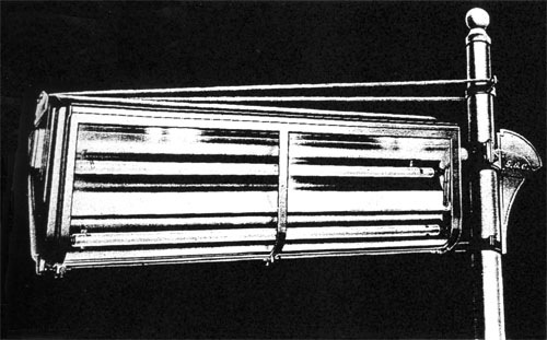
Z.8481. The lantern mounted on a special bracket.
|

FOUR
EIGHTY
LANTERN
|


|
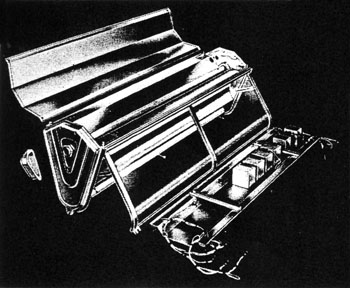
The lantern with the canopy and auxiliaries tray removed showing the bracket passing through
the lantern. The end cap has been taken off and the locking nut is seen screwed onto the
bracket end. The detachable tray is removed for the wiring of the chokes and capacitors which
can be seen mounted in position.
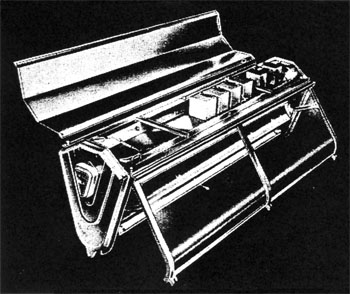
In the bottom illustration the tray is shown in position and the end cap replaced. Both
illustrations show one of the hinged doors held open, giving access to the lamps.

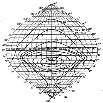
The Iso-candle is based on an average lamplight output through life from four 80 w. OSRAM
fluorescent lamps. (12,160 through lumens).
| Directional intensity ratio | 3.0 |
| Light above horizontal | 20% |
| Light output ratio | 75% to 80% |
|
"Four-Eighty" Fluorescent Lantern.
SPECIFICATION
Catalogue No. Z.8481
Use
25 ft. mounting height; spacing 100-150 ft.; broad roads up to 40 ft.
This lantern, Z.8481, is approximately equivalent to a normal main road lantern with a 400 w. H.P.M.V. lamp
and is used the same way. On account of its good colour rendering, it is most suitable for civic centres,
main shopping areas and promenade lighting at seaside resorts. The lantern has a very low surface
brightness.
Lamps
Four 80 w. OSRAM fluorescent lamps either Daylight or Warm White.
Pole Mounting
The lantern is primarily designed for mounting on a concrete or steel pole. It requires a horizontal
1½ in. gas barrel projecting 5 ft. 7 in. from the column. The last inch must be threaded. The
lantern, which is a sliding fit on the barrel, is held back against the column by a nut which screws
on to the threaded end of the bracket. When the latnern is in position water entry along the barrel is prevented by two packing
glands. Two Allen grub screws finally lock the lantern on to the tube, an additional fixing at the bottom
of the lantern secures it in a vertical position. A triangular plate on the front end of the lantern
is provided, when required, to give anchorage to wind stays.
Spanwire Mounting
When used for catenary wire suspension, double spanwire clamps are bolted on to each end castings,
and the two caps are supplied to conceal the sockets for the more normal bracket fixing.
Lantern Body
The body consists of two similar light alloy cast ends rigidly connected together by a top member of
sheet steel and a lower member of light alloy. The light alloy sheet roof, which is secured by six nuts,
is removable giving the access required for erection. it also discloses the detachable tray on
which are moutned the chokes, capacitors and starters wired to the lampholders. This tray with its
auxiliaries completely wired can be installed after the lantern has been erected and can be removed
for servicing at any time. An earthing screw is provided.
Doors
There is a full-length door of a cast light alloy, glazed with clear Perspex acrylic sheet on
each side of the lantern. The doors are hinged at the top and stays are provided to hold them open,
giving access to the lantern interior for cleaing and lamp replacement.
Focusing
The lamps are carried in specially positioned spring clips so that no focusing is necessary.
Optical System
On each side of the lantern there are two trough reflectors with specially designed contours.
These are firmly scrwed to shaped formers, one integral with each end casting and one in the centre.
The reflectors are constructed of super purity aluminium, polished, anodised and electrically
brightened and have a very high reflectivity. The reflectors are removable.
Weathering Finish
The alloy used is specially selected for its resistance to corrosion. Further protection is
obtained by the use of a suitable primer, undercoat and glossy aluminium finish top coat.
Erection Instructions
Full erection instructions are packed with each lantern.
Weight
(approx) 100 lbs. (45.3 kgs.) (without auxiliaries). 130 lbs. (59.0 kgs.) (complete with all auxiliaries).
Back to: GEC Street Lighting
|


