|
Specification Clearmain 8430
Use
Main road lighting; the lantern is designed for mounting at 25 ft. (7.62 m) and at spacing
120 ft (36.58 m) optimum, but can be used up to 150 ft. (45.72 m) maximum; road
width up to 30-40 ft (9.14 - 12.19 m).
Lamp
250W or 400W Osram mercury type MA/V lamp.
Mounting
Side entry. The lantern requires not less than 4 in. of horizontal unthreaded 1.1/4 in.
B.S.P. When fully home two 7/16 in. dia. Allen type grub screws grip the barrel. Water
running along the bracket arm is prevented from entering the lantern by a water baffle.
Lantern Body
Die-cast aluminium alloy. The body carries the reflectors, lampholder, terminal block,
heat resisting insulated wiring, lamp-steady, reflector plate, and universal magnetic
deflector. An earthing screw and porcelain cable cleat are provided.
Lampholder
Porcelain G.E.S. wired with heat-resisting insulated wire to a porcelain terminal block.
Over-Reflector
Immediately over the lamp is a hinged, non magnetic reflector. This can be lowered by
releasing the screw holding it, and gives access to the bracket entry and terminal
block. The reflector serves the dual purpose of reflecting light and preventing hot
air from over-heating the deflector.
Magnetic Deflector
On the reflector plate is mounted the universal magnetic deflector, which is in series
with the lamp and consumes 1 watt. The magnetic deflector can be used with either the 250W
or 400W MA/V lamp. The use of a magnetic deflector enables an MA/V lamp burning horizontally
to be operated with the same efficiency as the normal MA/V lamp.
Weathering Finish
The alloy used is especially selected for its resistance to corrosion. Further protection
is obtained by the use of a special one-coat aluminium finish stove enamel.
Optical System
The pressed prismatic refractor bowl (Z6630) is made of heat-resisting glass. The refractor
is secured in a die-cast light alloy ring which is supported on the main body casting by
a hinge and quick-release stainless steel toggle catch. The toggle has a safety catch
so that two distinct actions are needed before the refractor swings free. The first action
releases the toggle catch and lowers the hinged ring and refractor to a safety position,
where it is still held at each end. The toggle catch, which is at the bracket end,
can then be unhooked allowing the refractor to swing down, giving access to the lantern
interior. A gasket is fitted in the lower rim of the lantern body and when the
lantern is closed this makes a weatherproof joint with the hinged ring supporting
the bowl.
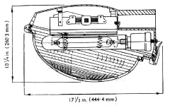
In use the lamp is mounted with its axis horizontal, and the plane of the rim of
the bowl at about 15° to the horizontal. By arranging for the lampholder to
be outside the bowl and the lamp to enter at an angle (patent applied for)
a compact lantern of small size is possible. The slight upward inclination of
the lantern towards the roadway in use directs maximum amount of light at night on to
the carriageway and adjacent area (verge, footwalk, side turning, etc.) on both sides,
and gives a very pleasing appearance to the lighting units by day. A good light output
ratio (67% - 70%) is obtained and very little light (not more than 8%) is emitted
above the horizontal plane through the light source.
 Groups of external shallow vertical fluting on the bowl help to distribute the
bright area over the greater part of the surface of the bowl as seen from normal
directions of view, thereby both adding to the attractive appearance and reducing
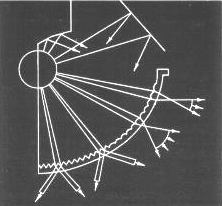
any possibility of discomfort glare. Light emitted upwards from the lamp is redirected
downwards by means of an auxiliary reflector system, of high reflectivity, so that,
in conjunction with the refracting elements of the bowl, it is re-disbributed to
suppliment the main distribution of downward light by the bowl.
Groups of external shallow vertical fluting on the bowl help to distribute the
bright area over the greater part of the surface of the bowl as seen from normal
directions of view, thereby both adding to the attractive appearance and reducing
any possibility of discomfort glare. Light emitted upwards from the lamp is redirected
downwards by means of an auxiliary reflector system, of high reflectivity, so that,
in conjunction with the refracting elements of the bowl, it is re-disbributed to
suppliment the main distribution of downward light by the bowl.
The main optical system consists of parallel refracting and diffusing prisms on the inside
of the glass bowl, the outer surfacing being substantially smooth to facilitate cleaning
and to avoid ledges and crevices where dirt can accumulate.
The prinicple of controlled diffusion, originated by the G.E.C. Research Laboratories
for lanterns using the H.P.M.V. lamp, has been adopted, so that in the main beam a
high intensity is obtained from a large area of relatively low brighness. The high
intensities at angles near the horizontal, essential for good road brightness with
normal spacing, are therefore achieved without objectional glare. Each main refracting
flute is designed in accordance with G.E.C. British Patent No. 507688, to contribute to
the peak intensity (at an angle between 79° and 75%deg; to the downward vertical),
and a significant proportion (decreasing with the intensity and with inclination to
the vertical) contribute light at lower angles. Cross-refracting prisms are used
on the lower part of the bowl to redistribute the more steeply downward light,
with intensity increasing at the wider angles up to peak direction.
The shape of the bowl has been specially designed to enable flutes of the nature
described to be used, whilst avoiding any "back" faces which give rise to losses of
light (patent applied for). No element on the inner surface of the bowl has any
face not used to direct light into a required direciton. Usually in a multiple prism
type refractor each prism has a "back" face, forming the step to the main refracting
face of the next prism. Although in a good design the inclination of such a face is
calculated so that the face intercepts as little light as possible, such a "back" face
always involves some wastage of light. By adopting a formation of flutes and prisms
which avoid the need for any "back" face, light losses from this cause are
eliminated.
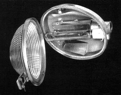 |
| The lantern with the refractor bowl lowered showing the lamp, reflectors and
general construction. |
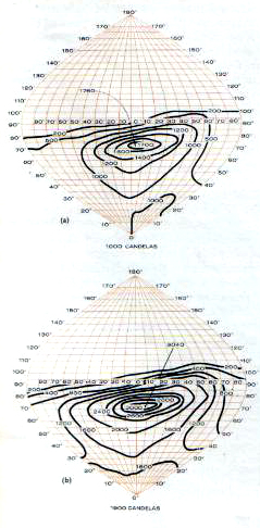
The iso-candela diagrams are based on an average lamp light output through life from:
(a) 250W Osram mercury type MA/V lamp (8,750 lumens average).
(b) 400W Osram mercury type MA/V lamp (16,000 lumens average).
| 250W | 400W |
| Directional intensity ratio | 2.0:1 | 1.9:1 |
| Light above horizontal | 7.5% | 8% |
| Light output ratio | 67% | 70% |
| Lumens in the lower hemisphere | 5,420 | 10,030 |
Light distribution data are given for the guidance of the lighting engineer and represent the
average results of laboratory tests on a number of lanterns taken at random from stock.
The data are based on the lamp characteristics stated; if the latest lamp efficiency is different,
the candela or lumen values should be calculated in direct proportion to the relative lamp
lumens.
Lantern weight: 18lb (8.16 kg).
|