|
Lamps
250W or 400W Truelite colour corrected mercury lamp.
Mounting
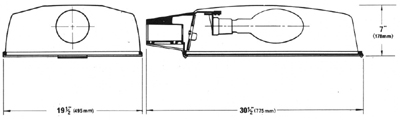
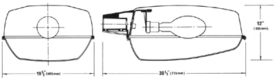
A side entry socket is provided to accept a 5 in. length of unthreaded 1¼ in. B.S.P.
Lampholder
Porcelain G.E.S wired with heat-resisting insultated wire to a porcelain terminal block.
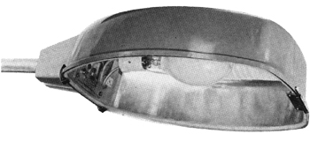
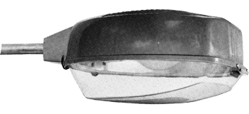
Construction
The lantern body is an aluminium pressing anodised inside and out, supported by an aluminium
alloy end casting. The body is enclosed by a hinged acrylic bowl or toughened glass plate
depending on the light distribution and lamp used.
The body pressing is accurately contoured so that the two sides form reflectors
to produce light distributions of either cut-off or semi cut-off as required, by B.S. 1788.
These alternative distributions are achieved with different sizes of lamp by a two
position lamp holder bracket and interchangeable enclosures. All cut-off versions of the
lantern are enclosed by a toughened flat glass; semi cut-off lanterns have moulded
acrylic bowls. When the lanterns are used with HPS lamps the enclosures have a slight
diffusing pattern.
The pressed body is supported by a die cast side entry casting sealed to one end, it is
provided with two concealed socket head screws for securing it to the bracket arm. Condensation
from the bracket is prevented from entering the lantern by a barrier.
The supply leads are sealed into the body of the lantern through flexible sleeving; this
method prevents dirt entering when the lantern breathes and ensures long intervals before
cleaning is necessary. A pure wool tropicalised felt gasket between body and enclosing bowl
filters any air entering through this joint.
All external fastenings for the enclosures - hinges and toggle catches are made in EN.58
stainless steel.
Weathering Finish
The alloy used is specially selected for its resistance to corrosion. Further protection
is obtained by the use of a pretreatment primer and stove enamel top coat.
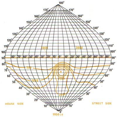
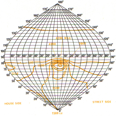
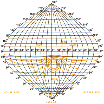
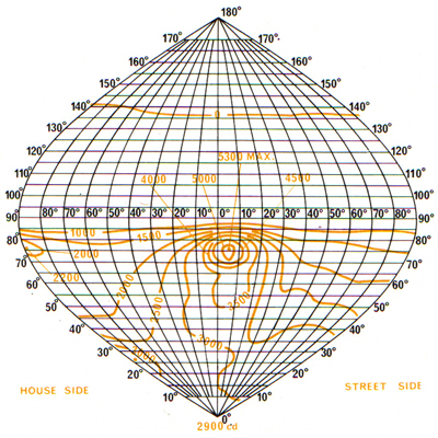
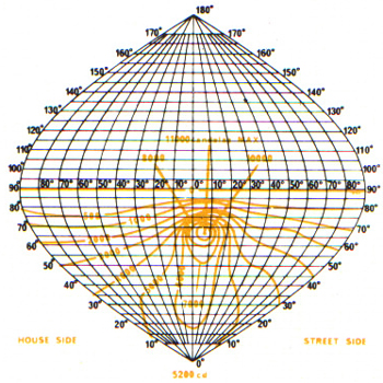
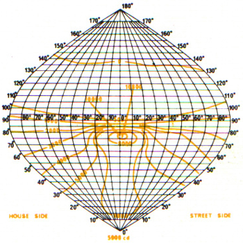
Illumination Data
|
|
| Light flux in lower hemisphere (lumens) |
7500 |
13500 |
See C.P. 1004 Tables 2-8 |
7800 |
13800 |
See C.P. 1004 Tables 10-16 |
| Downward light output ratio |
0.68 |
0.675 |
No limits specified |
0.71 |
0.69 |
No limits specified |
| Angle of elevation of upper limit of beam |
69° |
69° |
65° must be within beam |
77° |
77° |
75° must be within beam |
| Angle of elevation of lower limit of beam |
61° |
57° |
70½° |
68° |
| Peak Intensity Ratio |
3.2 |
2.7 |
2.0 to 4.0 |
3.4 |
2.4 |
1.8 to 4.0 |
| Max. intensity ratio in zone 0° - 30° |
1.8 |
1.79 |
0.3 to 2.0 |
1.55 |
1.58 |
0.3 to 1.7 |
| Min. intensity ratio in zone 0° - 30° |
1.5 |
1.4 |
0.45 |
0.66 |
| Max. intensity ratio in zone 0° - 30° / Peak intensity ratio |
0.56 |
0.66 |
0.77 max |
0.45 |
0.66 |
0.7 max |
| Angle at which 1.2 intensity ratio occurs above peak |
76° |
76° |
72° to 78° |
82½° |
82½ |
78° to 84° |
| Intensity ratio at the horizontal |
0 |
0 |
0.15 max |
0.13 |
0.14 |
0.6 max |
| Divergence of beam centre from the axis of the road in azimuth |
5° |
4° |
15° max |
5° |
4° |
15° max |
|