|
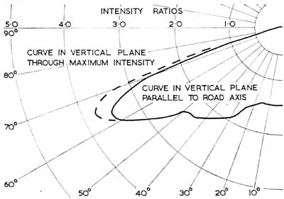
Type of Distribution
|
Cut-off
|
B.S. 1788:1964
requirements
|
250 WATT
MBF/U
|
400 WATT
MBF/U
|
|
Downward light output ratio
|
99%
|
98%
|
Angle of elevation
Upper limit of beam
Lower limit of beam
|
69°
60°
|
68°
58°
|
65° must be
within beam
|
Peak intensity ratio
|
3.8
|
2.935
|
2.0 - 4.0
|
Maximum and minimum intensity
ratios in the zone from the
downward vertical to 30° therefrom
|
1.934
1.301
|
1.875
1.525
|
not to exceed 2.0
not less than 0.3
|
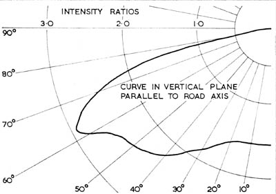
Angle of elevation at which the
intensity ratio is 1.2 in the vertical
plane parallel to the street axis
|
73°
|
77°
|
between 72°-78°
|
Intensity ratio at the horizontal
in the vertical plane parallel to
the street axis.
|
0.146
|
0.106
|
not to exceed 0.15
|
Angle of azimuth between
Beam centre and road axis
|
8°
|
0°
|
not to exceed 15°
|
Light output in lower hemisphere
(downward flux lumens)
|
6,425
|
12,013
|
See CP 1004
Part 2:
1963 tables
|
|
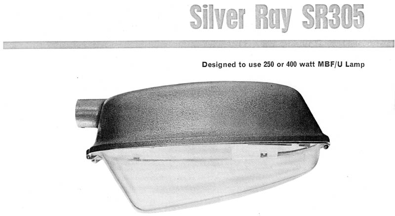
DIMENSIONS
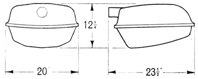
FIXING
Side entry 1¼" B.S.P plain
4" maximum length, secured by two
Allen screws.
Weight 14½ lbs.
|