(F) 708
WEATHERPROOF
LANTERNS |
|
|

WEATHERPROOF LANTERNS FOR STREET AND YARD LIGHTING
THE "WEMBLEY" LANTERN"
(Patent No. 217029)

FC. 6046/7
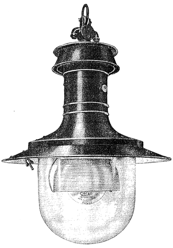
THE "WEMBLEY" LANTERN |

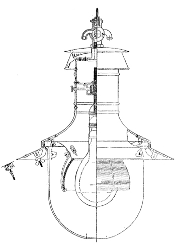
SECTIONAL ELEVATION OF "WEMBLEY" LANTERN |
BODY.
Spun from heavy gauge sheet copper, enamelled green outside, and white inside for relfecting surfaces with
copper top and ventilator.
VENTILATING DEVICE.
A patented device operating on the ejector principle is fitted combining extreme simplicity with high
efficiency. This device causes a steady stream of air to be drawn into the lantern and ejected from beneath the
top cowl. Exhaustive tests have been carried out with this ventilating device, special attention being given to
lamp performance. The result of these tests demonstrates convincingly that the ventilation is such as to
safeguard the lamp from overheating and consequent reduction in normal life.
WEATHERPROOF CONSTRUCTION.
The development of the "WEMBLEY" lantern to its present high state of efficiency was accompanied by periodical tests to
prove that it was absolutely weatherproof.
FOCUSING DEVICE.
This is a special patented feature which enables the lamp to be raised or lowered inside the prismatic refractor,
thus varying the distriubution of light to suit the height and spacing of units. All such adjustments in the larger
size "WEMBLEY" lanterns are made from the outside without opening the lantern in any way. The lamp is lowered until the
filament is sighted across the bottom edge of the refractor; the knob is turned a predetermined number of times to the right, and
adjustments can be made to the 1/100th part of an inch.
OPTICAL SYSTEM.
The "WEMBLEY" lantern is made in various sizes, designed to accommodate OSRAM gasfilled lamps or either 100 watts or
1500 watts, suitable for main thoroughfares, suburban streets and residential areas. It is equipped with a prismatic
glass refractor and white enamelled over-reflector, the lamp and refractor being protected by a clear glass outer globe.
PERFORMANCE.
The light emission is ideal for street lighting, the maximum candle-power being given at the useful angle of 70° from
the vertical. The resultant illumination curve from two such units suspended at a height of 25 feet from the ground and spaced 100
feet apart is shown by the curve below.

CURVES OF ILLUMINATION FROM TWO "WEMBLEY" LANTERNS
Showing horizontal illumination of a plane 3 feet above ground level, lanterns spaced 100 feet apart; suspension height
25 feet to filament; one lantern per standard, equipped with 1000-watt 100-volt zigzag filament OSRAM Gasfilled Lamp. The above
curves show :- illumination from single lanterns (indicated by continious line), illumination from both lanterns (indicated
by broken line).
| AVERAGE ILLUMINATION 1.75 FOOT-CANDLES |
MAXIMUM ILLUMINATION 2.89 FOOT-CANDLES |
| MINIMUM ILLUMINATION 0.90 FOOT-CANDLE |
| INEQUALITY RATIO = MAX ILLUMINATION / MIN ILLUMINATION = 3.2 |
SPACING RATIO = SPACING DISTANCE / HEIGHT = 4 |
The values shown are obtained on a horizontal plane 3 feet above ground leve, and it will be seen that the maximum illumation
occurs at aprrpoximately 4 feet from the base of the standards and is 2.89 foot-candles. The minium illumination is 0.90 foot-candle
and the average intensity is 1.75 foot-candles. Thus, with a spacing ratio of 4 to 1, which is in accordance with the best modern
practice, an inequality ratio (i.e. maximum illumination divided by minimum illumination) of 3.2 to 1 is obtatained - a highly
satisfactory figure. Distriubtion curves of other models will be furnished upon request.
| FC. 6046 |
"Wembley"
Street Lighting Lanterns |
1000 or 1500 |
24 |
2 9 |
22 |
5 0 |
5 |
On Application |
| FC. 6047 |
"Wembley"
Street Lighting Lanterns |
300 or 500 |
18 |
2 0 |
12 |
2 6 |
3 |
On Application |
|


