|
ilp archive : sheffield 1928
Held in Sheffield during July 9th - 12th.
"It was attended by a number of leading members of the
Illuminating Engineering Society and by representatives of the B.E.S.A. Committee on Street Lighting
to whom the practical demonstrations of methods of complying with the British Standard Specification BS 307
were natually of special interest."
"The outstanding item, however, was the execellent display of lighting fittings, in whcih practically
all the leading modern types were represented, distributed over approximately eight miles of streeets. A list of
these 50 experimental installations is reproduced here. Visitors were taken on tour round the lighted streets,
and had ample opportunities of judging their effect. They were also invited to participate in a series of tests,
chiefly directed to judgements of glare, the records being inscribed on appropiate cards specialy prepared for the
purpose."
"One was, however, struck by several salient points, such as the evident difficulty of devising installations
to comply with the higher classes of the specification, and the considerable part played by glare in most cases where
an attempt is made to secure approximately uniform distribution of light." - [Illuminating Engineer, August 1928, p215]
"On Thursday evening [after the conference] a meeting of the Committee of the B.E.S.A.
responsible for the framing of the Standard Specification had
been arranged."- [Illuminating Engineer, August 1928, p219]
| 1. |
Electric |
Lantern with Dome Refractor |
1000W |
|
|
|
91' |
51' |
28' and 25' |
|
0.700 |
2.000 |
1:3 |
C |
|
|
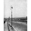
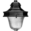
 Fitzalan Square, Sheffield.
GEC 1000-watt Wembley Lanterns with symmetric refractor.
See: The Illuminating Engineer, August 1928, p232 |
| 2. |
Electric |
Vitreous Enamelled, globeless type, lantern with trough reflectors |
750W |
Staggered |
Fig. 2 |
26' |
226' |
114' |
25' |
9.0 |
0.065 |
4.000 |
1:62 |
F |
|
|
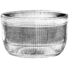
 Pond Street, Sheffield.
Benjamin 500-watt Rodalux lanterns. This instation was of a special type of
the Rodalux which took 750W lamps. "This form of lighting, which aims at spreading the light down the length of
the street and obtaining approximately uniform illumination works out economically in practice,
and one judged that the effect is obtained with a smaller degree of glare than often
occurs in such cases.
See: The Illuminating Engineer, August 1928, p234 |
| 3. |
Gas |
Square copper lantern; pre-heater with four nozzles in line; medium size mantles |
10 c.f. |
Staggered |
Fig. 2 |
33' |
82' |
45' |
13½' |
6.0 |
0.060 |
2.000 |
1:33 |
F |
| "Installations 2 and 3 form an interesting comparison. Installation 2
has large units erected at a considerable height and far apart. Installation 3 comes into the same class of the
specification with smaller units closer together and at a lesser mounting height. While the minima illumination
are almost identical (0.065 and 0.060 foot-candles) there is a considerable difference in the maxima
illumination (4.0 and 2.0 foot-candles.). But the increased maximum illumination in installation 2 does not
add a great deal to the visibility of the street." - [J. F. Colquhoun, Illuminating Engineer, August 1928, p220] |
| 4. |
Gas |
Square copper lantern; earthenware reflector; 2-light burner; bijou mantles |
3.5 c.f. |
One-sided lighting |
Fig. 5 |
29' |
96' |
54' |
13½' |
7.1 |
0.012 |
0.500 |
1:42 |
H |
| "Installation 4 is a good example of what ought not to be done. The
lamps are arranged on one side of the street only, and the installation comes within, in every respect, class H of
the specification. But the result is unsatisfactory. This suggests that a modification of the specification is
necessary. Perhaps it could be met by a clause giving minima mounting heights of the units on one-sided lighting
in relation to the width of the carriageway. Further, the distance between the lamps and on which the spacing-height
ratio is based is greater where the lamps are staggered than where they are placed
on one side of the street only. Hence, "effective" distance, i.e. the sum of the distances from
the test point to the two nearest lamps, should be taken." - [J. F. Colquhoun, Illuminating Engineer, August 1928, p220] |
| 5. |
Gas |
Square copper lantern; earthenware reflector; 2-light burner; bijou mantles |
3.5 c.f. |
Staggered |
Fig. 2 |
29' |
91' |
48' |
13½' |
6.7 |
0.016 |
0.500 |
1:31 |
H |
| "A comparison of installations 4 and 5 shows the great advantage
with low-mounted units of staggered lighting. There is an increase on the minimum illumination in
installation 5 over installation 4 of only 0.004 foot-candles, but the increase in visibility is considerable,
at all events on the carriageway." - [J. F. Colquhoun, Illuminating Engineer, August 1928, p220] |
| 6. |
Gas |
Square copper lantern; pre-heater with four nozzles in line; bijou mantles |
7 c.f. |
Staggered |
Fig. 2 |
33' |
108' |
57' |
13½' |
8.0 |
0.020 |
1.000 |
1:50 |
G |
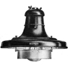
| 7. |
Gas |
Inverted type, with half-frosted and half-clear globe; four medium mantles in circle |
10 c.f. |
Staggered |
Fig. 2 |
33' |
80' |
44' |
13½' |
5.9 |
0.066 |
1.200 |
1:18 |
F |
|
|
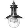
City Road, Sheffield.
Sugg Littleton lanterns. (See below).
See: The Illuminating Engineer, August 1928, p239 |
| 8. |
Gas |
Inverted type with clear glass globe; four medium mantles in circle |
10 c.f. |
Staggered |
Fig. 2 |
33' |
85' |
46' |
13½' |
6.3 |
0.050 |
1.700 |
1:34 |
F |
|
|
City Road, Sheffield.
Sugg Littleton lanterns. Upright "Littleton" lamps also equipped with
Horstmann controllers, were fitted in the City Road, 10 of the lamps being fitted with
clear globes and 10 with half-frosted globes similar to those used in Church Street.
See: The Illuminating Engineer, August 1928, p239 |
| "Installations 7 and 8 are identical except that No. 7 is fitted with
half-clear and half-frosted globes, and No. 8 with clear globes. The ratio of minimum to maximum illumination
is 1:18 with the half-frosted globes as against 1:34 with clear globes. The minimum illumination is increased
from .05 foot-candles in installation 8 to 0.66 in installation 7. This is largely due to the globes." - [J. F. Colquhoun, Illuminating Engineer, August 1928, p220] |
| 9. |
Gas |
Square copper lantern; four medium mantles in line |
10 c.f. |
Staggered |
Fig. 2 |
33' |
85' |
46' |
13½' |
6.3 |
0.060 |
2.000 |
1:33 |
F |
| "The advantage of mantles being placed "in line" rather than
"in circle" is shown by installation 9." - [J. F. Colquhoun, Illuminating Engineer, August 1928, p220] |
| 10. |
Electric |
Prismatic glassware bowl; 2-way |
75W |
Staggered |
Fig. 2 |
18' |
95' |
48' |
13½' |
7.0 |
0.035 |
0.300 |
1:7 |
G |
| 11. |
Electric |
Mirror reflectors |
75W |
Staggered |
Fig. 2 |
18' |
95' |
48' |
13½' |
7.0 |
0.033 |
0.400 |
1:11 |
G |
| 12. |
Electric |
Swan neck; enamelled reflector |
60W |
Staggered |
Fig. 2 |
16' |
95' |
48' |
11½' |
8.2 |
0.014 |
0.270 |
1:19 |
H |
| 13. |
Electric |
Ripple glass globes |
100W |
Staggered |
Fig. 2 |
16' |
95' |
48' |
13½' |
7.0 |
0.016 |
0.300 |
1:19 |
H |
|
|

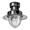
 Fretson Road, Sheffield.
BTH 100-watt Leeds Lanterns with ripple glass globes."The Fretson Road is in a residential district,
and the lanterns are in staggered formation. The pleasing appearance of this lantern makes it particularly suitable for residential districts.
The general lines of the lantern, combined with the exceptionally beautiful glass, give it a pleasing appearance by day as well as by night.
The "Leeds" lantern, which was designed by the BTH Company some time in advance of the conference, was on view, both diffusing and directional
devices being well represented. It appears to be specially successful in eliminating the difficulty of glare, which, by general consent,
has a prejudicial effect on visibility. One could not be struck by the important role played by the various optical arrangements modifying
the natural distribution of light from the source on which the possibility of obtaining moderate "diversity ratios" mainly depends."
See: The Illuminating Engineer, August 1928 and The Illuminating Engineer, August 1928, p238 |
| "Installations 10 and 11 may be constrasted with installations 13 and 14, the former
showing considerable uniformity of illumination and the latter considerable contrast. There is a difference in the
appearance of installations 10 and 11. The measurements of illumination are almost equal, but the surface brightness
on the roadway on installation 11 is greater than on installation 10. This may be due to difference in gradient
of the roadway, or to a difference in the distribution of light. But surface brightness is not necessarily visibility,
unless it is obtained by the silhouette effect when the bright surface of the roadway acts as a mirror.
In installation 10 the distinction in two colours, green and brown, can be clearly seen at a distance of 57 yards
when those colours are near the minimum test point. In installation 11 they cannot be distinguished beyond
32 yards. This is entirely due to the greater glare from light sources of installation 11 as compared with
installation 10." - [J. F. Colquhoun, Illuminating Engineer, August 1928, p220] |
| 14. |
Electric |
Vitreous enamelled reflector with glare screen |
100W |
Staggered |
Fig. 2 |
18' |
84' |
43' |
15' |
5.0 |
0.014 |
0.800 |
1:57 |
H |
| 15. |
Electric |
Copper lantern; dome refractor |
300W |
Centre Lighting |
Fig. 4 |
72' |
105' |
64' |
28' |
3.7 |
0.100 |
0.500 |
1:5 |
E |
| 16. |
Electric |
Copper lantern; dome refractor |
500W |
Centre Lighting |
Fig. 4 |
72' |
105' |
64' |
28' |
3.7 |
0.105 |
0.800 |
1:8 |
E |
| 17. |
Electric |
Copper lantern; dome refractor |
1000W |
Centre Lighting |
Fig. 4 |
72' |
103' |
63' |
28' |
3.7 |
0.500 |
1.550 |
1:3 |
C |
|
|
Prince of Wales Road, Sheffield.
GEC 1000-watt Wembley Lanterns with symmetric refractor.
See: The Illuminating Engineer, August 1928, p232 |
| 18. |
Electric |
Copper lantern; dome refractor |
1500W |
Centre Lighting |
Fig. 4 |
72' |
96' |
60' |
28' |
3.4 |
1.000 |
2.500 |
1:2½ |
B |
|
|
 Prince of Wales Road, Sheffield.
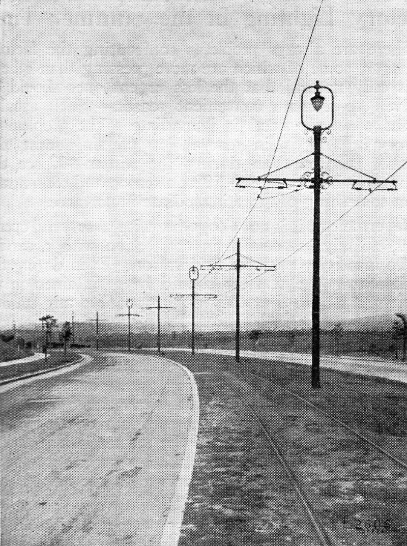
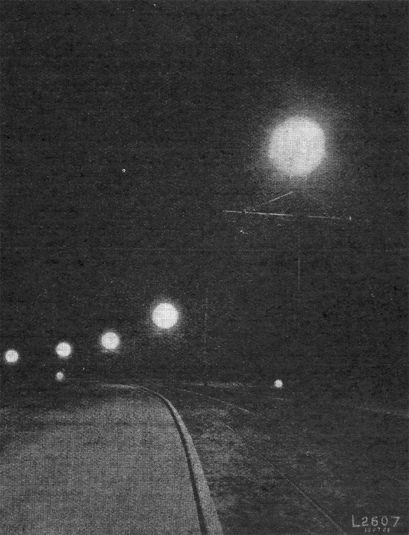
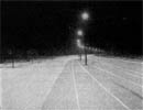
GEC 1500-watt Wembley Lanterns with symmetric refractor.The new Prince of Wales Road was planned in the form of a boulevard with
central double-rail tram track, and with a carriageway on either side for ordinary vehicular traffic. The centrally mounted lighting units make an imposing display.
In one section of the street, where 1500-watt lamps are used, the high minimum illumination of 1.0 foot-candle is attained. The effect of this
bright illumination is accentuated by the somewhat light colour of the roadway, and the effect of entering the fine road avenue from
a side road is quite striking. It illustrated, in fact, the desirability of "grading" the illumination in passing from main street to side
streets
See: The Illuminating Engineer, August 1928 and The Illuminating Engineer, August 1928, p230 |
| 19. |
Electric |
Copper lantern; dome refractor |
1000W |
Centre Lighting |
Fig. 4 |
72' |
109' |
65' |
28' |
3.9 |
0.335 |
1.600 |
1:5 |
D |
|
|
 "The Wicker", Sheffield.
GEC 1000-watt Wembley Lanterns.
See The Illuminating Engineer, August 1928 |
| 20. |
Electric |
Copper lantern; dome refractor |
500W |
Centre Lighting |
Fig. 4 |
72' |
96' |
60' |
28' |
3.4 |
0.200 |
0.800 |
1:4 |
E |
|
|
Prince of Wales Road, Sheffield.
GEC 500-watt Wembley Lanterns with symmetric refractor.
See: The Illuminating Engineer, August 1928, p232 |
| 21. |
Electric |
Copper lantern; dome refractor |
300W |
Centre Lighting |
Fig. 4 |
72' |
105' |
64' |
28' |
3.7 |
0.100 |
0.500 |
1:5 |
E |
|
|
Prince of Wales Road, Sheffield.
GEC 300-watt Wembley Lanterns with symmetric refractor.
See: The Illuminating Engineer, August 1928, p232 |
| "Installations 15 to 21 serve to demonstrate the higher "ratings"
of the specification." - [J. F. Colquhoun, Illuminating Engineer, August 1928, p220] |
| 22. |
Gas |
Square copper lantern; four bijou mantles in line |
7 c.f. |
Staggered |
Fig. 2 |
29' |
84' |
45' |
13½' |
6.2 |
0.050 |
1.000 |
1:20 |
F |
|
|
???, Sheffield.
Foster And Pullen Standard lanterns. This result was obtaiend by the use of 4-light
superheater burners in square lanterns, the burners, with No. 1 (Bijou) nozzles, being arranged to secure the maximum illumination
along the road. A feature of the "Avil" lanterns furnished by this firm is the robust and simple construction, the gas and air
regulators being absolutely positive in action, and all springs, sleeves or other parts liable to get out of order are
eliminated.
See: The Illuminating Engineer, August 1928, p239 |
| 23. |
Gas |
Square copper lantern; 5-light bijou mantles in circle, fed from roof. |
8.75 c.f. |
Staggered |
Fig. 2 |
29' |
78' |
42' |
13½' |
5.1 |
0.034 |
1.200 |
1:35 |
G |
| 24. |
Gas |
Square copper lantern; directive glassware; four bijou mantles in line. |
7 c.f. |
Staggered |
Fig. 2 |
29' |
75' |
40' |
13½' |
5.5 |
0.065 |
1.000 |
1:15 |
F |
| "Installation 24 shows an interesting adaptation of directive
prismatic glassware to gas street lighting." - [J. F. Colquhoun, Illuminating Engineer, August 1928, p220] |
| 25. |
Gas |
Square copper lantern; 4-light bijou mantles in circle; burner fed from roof. |
7 c.f. |
Staggered |
Fig. 2 |
29' |
100' |
52' |
13½' |
7.4 |
0.020 |
1.000 |
1:500 |
G |
| 26. |
Gas |
Square copper lantern. |
7 c.f. |
Staggered |
Fig. 2 |
29' |
78' |
42' |
13½' |
5.8 |
0.035 |
1.000 |
1:29 |
G |
| "A comparison of installation 22 with installations 25 and 26
again shows the value of gas mantles be placed "in line."" - [J. F. Colquhoun, Illuminating Engineer, August 1928, p220] |
| 27. |
Gas |
Square copper lantern. |
10 c.f. |
Staggered |
Fig. 2 |
29' |
78' |
42' |
13½' |
5.8 |
0.055 |
2.000 |
1:36 |
F |
| 28. |
Gas |
Swan-neck fitting; 5-light bijou mantles. |
8.75 c.f. |
Staggered |
Fig. 2 |
34' |
72' |
39' |
13½' |
5.3 |
0.050 |
1.500 |
1:30 |
F |
|
|
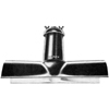
Staniforth Road, Sheffield.
Lighting Trades Ltd. Six square copper lanterns and six Silva lamps. The chief feature of this
exhibit was the incorporation of the "Renown" burner, an interesting novelty.
See: The Illuminating Engineer, August 1928, p240 |
| 29. |
Electric |
"Housing" lantern; enamelled reflector. |
500W |
Staggered |
Fig. 2 |
45' |
94' |
54' |
25' |
3.7 |
0.160 |
2.100 |
1:13 |
E |
| 30. |
Electric |
Two-way band refractor. |
500W |
Staggered |
Fig. 2 |
39' |
112' |
60' |
25' |
4.4 |
0.100 |
1.000 |
1:10 |
E |
|
|
Attercliff Road, Sheffield.
ELECO Glasgow lantern with 2-way Holophane band refractor.
See: The Illuminating Engineer, August 1928, p238 |
| 31. |
Electric |
Floodlight type |
(Impossible to give average distance between lamps, or space-height ration, because they are not normally spaced.) |
|
|
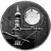
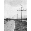
 ??? Road, Sheffield.
Lewenz & Wilkinson Limited Blaizolite lanterns.These lanterns have been extensively used for the illumination
of large exterior areas such as railway sidings, colliery works, quarries, harbours, etc. Their application to stret lighting was in the nature
of an experiment. The lanterns were moutned in diagonally opposing pairs with their backs to the oncoming traffic, the idea being to flood the
street with light. Distances between opposing pairs will usually vary from about 120 yards for main streets in a city to 200 yards on arterial
roads etc. The slanting rays have been found very adventageous in showing up unevenness of the roadway. The lantern recommended
for street lighting is equipped with a 500W lamp. The application of these units to street lighting was a novel step. The illumination
appeared to be good, but the "clock-like" appearance of the unit is somewhat unusal in street lighting. To anyone facing the unit
the brightness was rather high - though not more so than some other installations in which glare at angles slightly below the
horizontal seems to be an almost inevitable result of efforts to obtain a low diversity factor. Naturally, the conditions applying
in this case were somewhat different from those under which such units would ordinarily be used, the height of suspension, for instance,
being less than that ordinarily adopted for floodlighting large areas. This particular installation hardly fell within the
ordinary requirements of the Specification. But such units may neverless have useful applications for lighting squares and in
other cases in which something in the nature of floodlighting is desirable, whilst for the lighting of arterial roads, where
from motives of economy the distance apart of units is necessarily large, they may also have interesting possibilities.
See: The Illuminating Engineer, August 1928, p238 |
| "Installation 31 is of special interest. It is an endeavour to apply
a form of floodlighting to street lighting. It does not conform to the specification in any particular. There
are eight lamps (500-watt) in 710 feet of roadway 42 feet wide. The average spacing for normal lighting
would be 97 feet between the lamps and 54 feet from the test point to the two nearest lamps." - [J. F. Colquhoun, Illuminating Engineer, August 1928, p220] |
| 32. |
Electric |
Dome mirror reflector fitted with diffusing screen. |
500W |
Staggered |
Fig. 2 |
37' |
120' |
64' |
25' |
4.8 |
0.080 |
1.200 |
1:15 |
F |
|
|
 Attercliff Road, Sheffield.
Kamdem Mirrorlite Unit with new diffusing band.
See: The Illuminating Engineer, August 1928, p234 |
| 33. |
Electric |
Dome mirror reflector only. |
500W |
Staggered |
Fig. 2 |
37' |
93' |
52' |
25' |
3.7 |
0.100 |
1.200 |
1:12 |
E |
|
|
Attercliff Road, Sheffield.
Kamdem Mirrorlite Unit in ordinary configuration."There were six ordinary "Mirrorlite" lanterns, three being
of the ordinary type and three with the new diffusing band - the latter installed in the section of the rod lined by houses in order to illustrate
the effect of this band in diffusing light upwards. The comparison of these two types of unit was most instructive. Of late years there has been a
distinct tendency to adopt concentrating opaque reflectors for street lighting. This methods inevitably leads to a somewhat high diversity factor,
though the special inner prismatic reflector adopted in the ordinary "Mirrorlite" is design to give an improvement in this respect. But any lack in
uniformity of illumination is considered to be more than counterbalanced by the fact that the lighting units filament of the lamp is completely
screened. Certainly the installation of these units was comparatively free from glare, though naturally the bright surface of the inner reflector
was visible at some angles. The adoption of the diffusing band struck one as a distinct improvement from the standpoint. Apart from its primary advantage
of diffusing a certain amount of light upwards and prevening a hard shadow line on adjacent buildings, the diffusing ring helps further to
eliminate glare and gives a softer and more pleasing effect. It is worth noting that the minimum illumination on the roadway was almost the same -
0.1 foot-candle with the simple reflector, and 0.08 when the diffusing band was employed - so that the latter evidently did not materially
diminish the intensity in the street notwithstanding the higher illumination on surrounding objects."
See: The Illuminating Engineer, August 1928, p234 |
| "More might be made of installations 32 and 33. The minima of
illumination are needlessly low. A minima more than double the present figures could be obtained, but
there were some circles of bright light on the ground and the makers did not like it." - [J. F. Colquhoun, Illuminating Engineer, August 1928, p220] |
| 34. |
Electric |
Directive glassware, 2-way bowl. |
500W |
Staggered |
Fig. 2 |
39' |
114' |
61' |
25' |
4.5 |
0.225 |
1.600 |
1:7 |
D |
|
|
Attercliff Road, Sheffield.???
Possibly Holophane refractor.
See: The Illuminating Engineer, August 1928, p232 |
| "Installations 30 and 34 are 2-way directive refractors.
The magnification in installation 34 is approximately 8, and in installation 30 somewhat less than 8. One is
conscious of glare in installation 34; it does not seem discomforting on the roadway, but it is slightly so
at certain places on the footpath." - [J. F. Colquhoun, Illuminating Engineer, August 1928, p220] |
| 35. |
Electric |
Directive glassware, band. |
500W |
Staggered |
Fig. 2 |
39' |
114' |
61' |
25' |
4.5 |
|
|
|
|
| 36. |
Electric |
Enamelled reflector with glare screen. |
500W |
Staggered |
Fig. 2 |
40' |
109' |
59' |
25' |
4.3 |
0.140 |
2.500 |
1:18 |
E |
|
|
 Attercliffe Road, Sheffield.
Benjamin 500-watt Biflector lanterns. These units proved quite effective,
the screening effect against glare being particularly noticeable.
See: The Illuminating Engineer, August 1928, p234 |
| 37. |
Electric |
Dome refractor. |
500W |
Staggered |
Fig. 2 |
40' |
117' |
63' |
25' |
4.6 |
0.105 |
1.700 |
1:16 |
E |
| 38. |
Electric |
Refractor bowl, 2-way. |
300W |
Staggered |
Fig. 2 |
40' |
106' |
57' |
25' |
4.2 |
0.225 |
0.450 |
1:2 |
D |
|
|
 Savile Street, Sheffield.
Six Metrovick 300-watt Caledon Lanterns with two-way non-axial Holophane refractor
bowls. The carriageway at this point is 40 ffeet wide, and the average distance between the lamps is 106 feet. The lanterns
are mounted at a height of 25 feet on brackets projecting 6 feet over the carriageway. The minimum illumination was 0.25 foot-candle,
the maximum 0.45. The diversity coefficient (ratio of maximum to minimum illumination) was thus only 2 - a remarkably low value.
The installation comes within Class "D" of the Specification, and arouse much discussion, one of the chief questions being
whether the effect was liable to be monotonous. On this point some difference of opinion seemed to exist. In the course of the tests
the interesting discovery was made that better results, as regards visibilty, were obtained when 300-watt lamps were substituted for
500-watt ones. It is believed that this was largely due to the nature of the lanterns, which gave results comparable with
those obtained with many lanterns of the 500-watt type - an important consideration in view of the difference in cost of current
for operation..
See: The Illuminating Engineer, August 1928, p236 |
| "Installation 38 led to an interesting experience. The magnification
of the refractors used is approximately 12, and with 500-watt lamps fitted the glare was distinctly harmful.
Observers expressed their opinion of it as "insufferable", "very objectional," "objectional,"
"discomforting." Visibility was distinctly impaired by it, and on that point the observers were unanimous.
The 500-watt lamps were taken out and 300-watt put in. The glare was very considerably reduced and there was
marked improvements in visibility. On this point also the observers are unanimous, and
it is interesting to note that it is possible with certain fittings to improve visibility by reducing the
size of the lamp used with them." - [J. F. Colquhoun, Illuminating Engineer, August 1928, p220] |
| 39. |
Electric |
Directive glassware, asymmetric. |
500W |
Staggered |
Fig. 2 |
40' |
112' |
62' |
25' |
4.5 |
0.300 |
0.750 |
1:2½ |
D |
|
|

 Savile Street, Sheffield.
GEC 500-watt Wembley Lanterns with new asymmetric refractor.
See: The Illuminating Engineer, August 1928, p232 |
| "Installation 39 is similar to installation 34. The magnification
is approximately 6, and there is in consequence a reduction in the amount of glare." - [J. F. Colquhoun, Illuminating Engineer, August 1928, p220] |
| 40. |
Electric |
Prismatic glassware. |
1000W |
Centre Lighting |
Fig. 4 |
67' |
112' |
63' |
27½' |
4.0 |
0.350 |
1.700 |
1:5 |
D |
| 41. |
Electric |
"Housing" type lantern, large enamelled reflector. |
1000W |
Centre Lighting |
Fig. 4 |
46' |
114' |
60' |
27½' |
4.2 |
0.320 |
1.900 |
1:8 |
D |
| 42. |
Electric |
Enamelled trough reflector. |
500W |
Staggered |
Fig. 2 |
33' |
121' |
63' |
22;' |
5.5 |
0.130 |
2.600 |
1:2 |
E |
|
|
Blonk Street, Sheffield.
Benjamin 500-watt Rodalux lanterns. Six of the ordinary form [of Rodalux lanterns], equipped with 500-watt lamps,
were used in Blonk Street (minimum illumination 0.13 foot-candle). This form of lighting, which aims at spreading the light down the length of
the street and obtaining approximately uniform illumination works out economically in practice,
and one judged that the effect is obtained with a smaller degree of glare than often
occurs in such cases.
See: The Illuminating Engineer, August 1928, p234 |
| 43. |
Electric |
Band refractor. |
1000W |
Staggered |
Fig. 2 |
50' |
111' |
62' |
25;' |
4.5 |
|
|
|
|
| 44. |
Gas |
10 light medium mantles. |
25 c.f. |
Staggered |
Fig. 2 |
31' |
74' |
41' |
15' |
5.0 |
0.250 |
3.000 |
1:12 |
E |
|
|
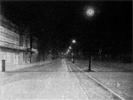
 Church Street, Sheffield.
Sugg Rochester lanterns. Sugg had fitted 13 10-light "Rochester" suspension lamps fitted on
wrought-iron swan-neck supports. These lamps were equipped with Horstmann automatic controllers. Special globes, frosted
over the lower half, were provided. This installation excited much favourable comment, attention being drawn to the good conditions of
visibility secured, notwithstanding the relatively low height of the posts.
See: The Illuminating Engineer, August 1928, p239 |
| "Installation 44 is in class D for minimum illumination but in
the lower class, E, for mounting height. Once would expect objectionable glare because of this but it is absent." - [J. F. Colquhoun, Illuminating Engineer, August 1928, p220] |
| 45. |
Gas |
Similar to 44. |
|
|
|
|
|
|
|
|
|
|
|
|
| 46. |
Electric |
Lantern with dome refractor. |
1000W |
Staggered |
Fig. 2 |
36' |
125' |
66' |
25' |
5.0 |
0.500 |
2.000 |
1:4 |
C |
| "Installation 46 is very uniform in illumination but is not
depressingly so. In viewing the installations one is struck by the fact that effective illumination is not
always attractive illumination." - [J. F. Colquhoun, Illuminating Engineer, August 1928, p220] |
| 47. |
Electric |
Enamelled reflector, opal lamps. |
300W |
Centre Lighting |
Fig. 4 |
72' |
96' |
60' |
28' |
3.4 |
0.080 |
0.800 |
1:10 |
F |
| 48. |
Electric |
Ripple glass globes. |
300W |
Centre Lighting |
Fig. 4 |
72' |
130' |
74' |
28' |
4.6 |
0.043 |
0.300 |
1:7 |
G |
|
|
 Prince of Wales Road, Sheffield.
BTH 300-watt Leeds Lanterns with ripple glass globes.
See: The Illuminating Engineer, August 1928 and The Illuminating Engineer, August 1928, p238 |
| 49. |
Electric |
2-way band. |
500W |
Staggered |
Fig. 2 |
34' |
120' |
63' |
25' |
4.8 |
0.120 |
0.850 |
1:7 |
E |
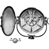
| 50. |
Electric |
Mirror reflector. |
500W |
Staggered |
Fig. 2 |
33' |
114' |
60' |
25' |
4.6 |
0.275 |
0.825 |
1:3 |
D |
|
|
 Attercliffe Road, Sheffield.
ESLA 500-watt Bi-Multi reflectors.
[This fitting] utilizes an ingenious combination of mirrors to give an exceptionally high
"multiplication factor"; it is stated that along the length of the street the candle-power is
approximately seven times as great as that given by the lamp alone. In this installation the
"Unit" system bracket has been used to bring the height of the short columns up to that specified
in the Standard Specification, thus illustrating how public lighting engineers can deal with the
problem of adjusting the heights of existing posts when bringing installations into line with the
Specification's requirements.
See: The Illuminating Engineer, August 1928, p236 |
Exhibitors included the Bland Light Syndicate Limited who were demonstrating a new street lamp cluser for gas lanterns.
"Possibly lighting with a minimum below 0.1 foot-candles may be helped out in attractiveness by
constrast of illumination. Lighting with a minimum above 0.1 foot-candles may not need that contrast.
Installations equal in minima illumination are equal in effectiveness. If they differ in maxima illumination
they differ in attractiveness and only very slightly in effectiveness. The one with the greater contrast is
the more attractive so long as the ratio minimum to maximum illumination does not exceed about 40. Over that figure
contrast seems to become unattractive. All this, of course, is assuming that installations are free from
objectionable and discomforting glare." - [J. F. Colquhoun, Illuminating Engineer, August 1928, p222]
"Brightness of the road surface, brought about by the rays of light striking the roadway at
oblique angles, does help the effectiveness of the illumination on the road surface, but it is difficult
to do this without creating tiring, harmful, or at least discomforting glare, which in its turn impairs
visibility." - [J. F. Colquhoun, Illuminating Engineer, August 1928, p222]
"The coefficient for glare (G) has not been given in the table as there is not a properly equipped
photometric laboratory in the Lighting Department of Sheffield, and it is a slow, laborious and unsatisfactory
job measuring the illumination on the street itself and arriving at the figures by calculation. However, the
figure was obtained for some of the more glaring installations. In no case was the value of "G" found
to be over 10." - [J. F. Colquhoun, Illuminating Engineer, August 1928, p222]
"Does the demonstration prove the specification? I think it does. If the installations are arranged
in the order of their minima illumination they do form themselves into what would be the order of
preference from teh point of view of effectiveness. But if arranged in their order of maxima illumination
one finds, again from the point of view of effectiveness, obvious contradictions." - [J. F. Colquhoun, Illuminating Engineer, August 1928, p222]
"The glare clause might be made mandatory in order to prevent of handicap an installation with a high
minimum illumination and considerable glare, and certainly something should be done to prevent an installation
such as No. 4 coming within the specification." - [J. F. Colquhoun, Illuminating Engineer, August 1928, p222]
"On the whole the specification has come through the test of this demonstration creditably, and it should be
put into operation in every city and town in the country. If this is to be done properly lighting departments
will require to be much better staffed and equipped in the future than they are now." - [J. F. Colquhoun, Illuminating Engineer, August 1928, p222]
"But, on thewhole, experience confirmed the impression that the accentuation of candle-power at
angles slightly below the horizontal in order to achieve approximately uniform illumination has drawbacks;
some of the installations which were most successful in this respect were also those in which glare seemed most
manifest. There was just one other type of installation one would like to have seen exploited - i.e.
that involving a sharp "cut-off" in order to screen distant lights completely, on the lines suggested by
Dr. Walsh at the Public Works and Transport Congress last yeaer. Whilst no doubt open to objection from other
standpoints, this method might have given instructive results in regard to the effect of glare on
visibility." - [Illuminating Engineer, August 1928, p230]
"This is probably the first time that an experimental street lighting isntallation on such a scale has been
attempted - certainly the first time in this country, and it should serve as an instructive object lesson to lighting
authorities throughtout the country." - [Illuminating Engineer, August 1928, p240]
|
|
Presidential Address
J. F. Colquhoun
|
|
|
Non-Manual Control of Public Street Lighting
E. H. Horstmann
|
|
|
Non-Manual Control of Public Electric Lighting
E. E. Sharp
|
|
|
What the Public Want from a Street Lighting Department as Pedestrians, as Motorists, as Ratepayers
Councillor F. Thraves
|
|
|
The Visibility of Objects in Artificially Lighted Streets
J. M. Waldram
|
|