|
leeds
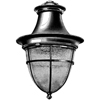
This street-lighting lantern consists of a canopy made of copper spinning reinforced with wrought-iron
spider, and a globe cage in basket form consisting of wrought-iron strips attached to a cast ring. The globe is
of BTH "Nelite" glass. An all-porcelain lampholder and inner reflector in white vitreous enamel are employed.
The BTH "Nelite" glass globe is of the rippled variety with a trace of opal, giving excellent diffusion,
but not materially interfering with the directional control. When lighted at night, the rippling gives the
effect of innumerable minute crystals which give life and sparkle to the lantern, which is not found with
plain opal globes. At the same time there is an absence of glare. The rippling also has the advantage
of making the globe practically self-cleaning, since rain falling on it is drained off naturally by the
small channels, and carries away a good proportion of any dirt that may have collected.
|
|
???
|
??? GLS
|
???
|
Top Entry
|
No Gear
|
1928 Journal
|
|
|
|
mercra "h"
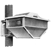
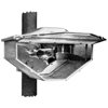 The first lantern to horizontally burn a mercury discharge lamp. Introduced in 1934.
A patented magentic deflector
is incorporated in the lantern to allow a standard 400W or 250W Mercra lamp to be burned in
a horizontal position.
The first installation is in Bromford Lane, Birmingham. Suitable for the lighting of wide
thoroughfares.
In common with all new departures, however, certain manufacturing difficulties were
experienced which prevented the lantern from being marketed at a competitive price.
General adoption of the lantern was not possible except in those places where a high
standard of lighting was more important than the capital cost. This led to a further
three years of research work leading to an improved, remodelled version of the lantern.
|
|
???
|
250-400W MA/H
|
GES
|
Pole clamp
|
No Gear
|
1935 Advert
1936 Advert
1936 Advert
1937 Journal
|
|
|
|
diron
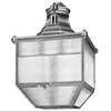
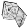 For main road lighting. Uses a series of internal reflectors and refractors and then
exterior plate refractors to create its lighting distribution. The top-cap and canopy of the lantern are
cast in aluminium alloy - a lightweight material having excellent weather-resisting properties. The
remainder of the lantern is of fabricated copper construction. Two phosphor-bronze eyebolts pivoted
on phosphor-bronze pins, mounted on the top canopy, hold the top-cap and the main body together. A
watershed designed to drain off any condensation is mounted between the top-cap and the canopy.
Erection involves mounting the top-cap on the bracket, making connections to the terminals on the
watershed, lifting the main lantern body into position and drawing the eyebolts up tight. The top-cap
thus forms a connection chamber. The system of reflectors and refractors consists of: (1) A sheet-steel
vitreous enambled reflector mounted in the lantern; (2) Two pot opal reflectors mounted on the kerb side
of the lantern; these throw the light clear of the buildings and symmetrically in either direction
up and down the road. The space between the reflectors and the main lantern body is blanked off to
prevent dust accumulating; (3) Two flashed opal reflectors mounted on the road side of the lantern to
cut down the light thrown across the road and at the same time to throw the light symmetrically in
either direction down the road; (4) Two refractors mounted within the lantern which serve to deflect
on to the road a proportion of the light which would normally fall onto the pavement.
|
|
Type 304-B3
|
400W MA/V
|
GES
|
Side Entry
|
No Gear
|
1936 Advert
1936 Paper
1936 Advert
1939 Advert
1939 Journal
1944 Journal
|
|
|
|
dilen
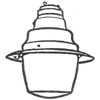 A general purpose lantern of simplified design. Introduced in 1936. Fitted with a
prismatic bowl and could be used with either mercury vapour or tungsten filament
lamps. Manufactured in two sizes: one could take 250-400W MA/V and a smaller
size was used with 150W MA/V. A simplified side
entry model was introduced in 1939 after the engineering
success of the Sodra "H" lantern. Available with either prismatic bowl or opal bowl. The opal bowl
version was designed to meet the demand for a lantern giving symmetrical distribution of light
without glare. The top cap is cast-iron and threaded 1¼" B.S.P. to screw directly onto a bracket
arm. Three bolts, fitted with locking devices, pass through the top cap to support the main body. The
mian body is spun from heavy guage copper, reinforced internally by cadmium plated steel spinning,
and carries a watershed fitted with two insulted terminals. Also mentioned as popular in 1945.
|
|
Type 100-A7
|
???W GLS
150W MA/V
|
???
|
???
|
No Gear
|
1936 Journal
1936 Advert
1937 Advert
1937 Advert
1937 Journal
1939 Programme
1944 Journal
1945 Programme
|
|
Type 100-A7
|
???W GLS
250-400W MA/V
|
???
|
???
|
No Gear
|
1936 Journal
1936 Advert
1937 Advert
1937 Advert
1937 Journal
1939 Programme
1944 Journal
1945 Programme
|
|
|

|
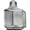
diref
Introduced in 1936. An open reflector type of lantern with well-glass for
side street lighting. Suitable for the lighting of narrow thoroughfares.
|
|
???
|
150W MA/V
250W MA/V
|
GES
|
Top Entry
|
No Gear
|
1936 Journal
1936 Advert
|
|
|
|
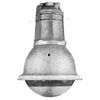
ranger
Introduced in 1936. Intended for side mounting and is particularly
applicable where there are tram or trolleybus standards spaced at 120'.
Its water trap prevents damage to the lamp due to water entering through
faulty joints or condensation in the bracket. It uses a simple refractor
and reflector for light control. The cap and body of the lantern are constructed from high-grade
cast-iron. All screws and nuts are brass. The glazing frame and canopy are one-piece sheet copper.
The canopy is fixed to the body by means of screws. The cap issecured to the body by two long
studs of which only two short lengths are threaded. With the lantern in the operating position the
upper thread is engaged in the body, but with the lantern in wiring or suspended position, the
lower thread is engaged. The watershed carries the porcelain lampholder and two insulated terminals
marked LINE and NEUTRAL, permanent connection being made between the lampholder and terminals by
asbestos insulted flexible leads. The watershed prevents any moisture due to condensation or joint
leaks from reaching the lampholder and lamp. And earthing terminal is also provided on the watershed.
The hinged bottom panel is stiffened by an added frame and is secured by a simple sliding catch.
|
|
Type 301-A3
|
250W MA/V
|
GES
|
Side Entry
|
No Gear
|
1936 Advert
1939 Journal
1944 Journal
|
|
|
|
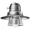
crown
A general purpose lantern. Strongly constructed and embodies certain unique features which
reduces maintenance to a minimum. Lamp adjustment and focussing are obtained by the two knurled
knobs on the cap, one for height and the other for the horizontal plane. The height adjustment
knob is attached to a screwed spindle passing through two bushed clamping plates. Between the clamping
plates is fitted a ball member which carries the lamp holder. This ball is released for horizontal
adjustment by means of a spindle which rotates a screwed bush in the clamping plates so releasing,
or clamping, as desired. The reflector sits on four phosphor-bronze springs and held firmly in position
by a spring mounted baffle, which fits the top of the reflector. This baffle prevents accidental
contact with the live parts of the lampholder.
|
|
300
|
300-500W GLS
|
GES
|
Top Entry
|
No Gear
|
1936 Advert
1939 Journal
1944 Journal
|
|
|
|
|
|
|
|
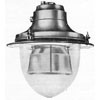
county junior
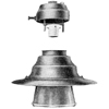 Especially designed for the new 80W and 125W MB lamps and introduced
in early 1937 at around the same time as the lamps. For Group B roads. It was
stressed that the lantern could also acccomodate 60-200W GLS and was fitted
with a focusing device (unlike most lanterns of its type and price). Weighs 7½lbs.
There are three main parts of the lantern body: the top cap (cast iron),
main spinning (heavy gauge copper) and reflector (sheet steel vitreous
enamel). The lampholder is fixed on a focussing carriage actuated by
one knurled knob. The glassware and reflector can be removed
from the lantern by removing one screw for cleaning. Light redirection achieved by
means of a special one-piece refractor band which is arranged to give a singly
axially asymmetrical form of light distribution. Vertical prisms are formed on the inside
to produce the required brightness distribution on thr road surface.
|
|
???
|
60-200W GLS
80-125W MB/V
|
BC
3BC
|
Top entry
|
No Gear
|
1937 Advert
1937 Advert
1937 Journal
1937 Advert
1937 Journal
1937 Programme
1939 Journal
1939 Journal
1944 Journal
1945 Programme
|
|
|
|
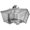
county cadet
Designed as a general purpose lantern for side street lighting with a low wattage lamp.
|
|
Type 300
|
60-200W GLS
80-125W MB/V
|
BC
3BC
|
Top entry
|
No Gear
|
1944 Journal
1945 Programme
|
|
|
|
mercra "h"
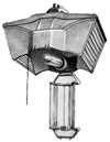 The newly designed Mercra "H" lantern is introduced in 1937. First exhibited
at the APLE's Folkestone Conference with an trial installation along Sandgate Road.
Improved and less
expensive version of the original model. Highly efficient unit for the lighting of main and
arterial roads as it incorporates the BTH Controller Cut-Off Principle. Designed for side mounting.
The rectangular light distribution curve makes the lantern particularly suitable for the
lighting of wide thoroughfares. Weighs 28lb and the finish is Battleship Grey.
A horizontally disposed line source of light
lends itself to simple optical control with higher efficiency of utilisation. The horizontal light
source, gives greater accuracy of light control, in both vertical and horizontal planes, than in
possible with vertically burning lamps. A sharp
cut-off is provided
below the horizontal, obviating glare and increasing the amount of light available for the
illumination of the road surface.
This modified lantern is designed for side mounting and incorporates a patented magnetic deflector
which makes it
possible to burn horizontally standard 250 watt or 400 watt Mercra Lamp. (This also
simplifies lamp stocks.) It is constructed mainly of non-corrosive
aluminium alloy and weighs 28 lbs. The reflectors are made of a special quality anodised-aluminium which is durable
and easily cleaned, and is highly efficient optically. Two years later the latern is
still extremely popular despite
A.R.P. expenditure. The optical system is now described as a "controlled cut-off" (which
is a semi-cut-off). The patented
method of mounting the top reflectors ensures the preservation of correct contour, while the
simplicity of wiring and
connecting, accessibility of the whole unit for cleaning, make for economical and trouble-free
operation. The light output is redirected to give a wide beam along the road, maintained to a high
value of 25° on the road side and 10° on the kerb side. Full advantage is thereby taken of
the reflecting properties of the road surface and surrounds. The beam is maintained at a high
intensity in the vertical plane to an angle of 86° At a mounting height of 25', this represents
a distance of 350' so that with normal staggered formation and a spacing of 150', the road brightness
is maintained completely from one unit to the next in the same line. Above 86° in the vertical
plane, the candle power is graded to a low value at the horizontal, this controlled cut-off thus almost
eliminating glare. The light source is still left visible, to maintain uniform accommodation of vision
of the eye.
|
|
Type 320
|
250-400W MA/H
|
GES
|
Top Entry
|
No Gear
|
1937 Advert
1937 Journal
1938 Advert
1938 Journal
1938 Advert
1938 Journal
1938 Advert
1938 Journal
1939 Advert
1939 Advert
1939 Programme
1939 Paper
1944 Journal
1945 Programme
1945 Paper
|
|
|

|
sodra "h"
After the success of the Mercra "H" lantern with its controlled cut-off
optics (semi-cut-off), the firm introduce this sodium version of the lantern
in 1939 for all sodium lamp types. The lantern is side-entry but an adaptor is available
for a top-entry option. (Provision for side entry allows
the design to be simplified and for less metal to be used
in the body of the lantern.) Aluminium alloy is used throughout the
lantern with the exception of the reflectors which are of
anodised aluminium of high purity. It is designed to give, at an angle of 84° representing a distance of 240' at the customary 25' mounting height
an intensity of over 75% of the main beam thus ensuring a continious surface brightness as far as the road surface will
permit. The two refractor panels diffuse the light and tend to eliminate glare, as well as redirecting downward a large
amount of light which would otherwise be wasted. Suitable for lighting wide roads.
|
|
???
|
45 SO/H
|
BC
|
Side Entry
|
No Gear
|
1939 Programme
|
|
???
|
60 SO/H
|
BC
|
Side Entry
|
No Gear
|
1939 Programme
|
|
???
|
85 SO/H
|
BC
|
Side Entry
|
No Gear
|
1939 Programme
|
|
???
|
140 SO/H
|
BC
|
Side Entry
|
No Gear
|
1939 Programme
1940 Journal
|
|
|
|
circra
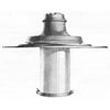
Designed to give a circular dispersive light distribution so well suited for the lighting of
open spaces, car parks, or central suspension street lighting systems. Top cap is cast iron and
tapped to 1" B.S.P. Side entrance for cables is also provided in the cap and screwed ¾" B.S.
conduit - this opening is normally sealed with a removable plug. The cap carries a copper canopy
to which the lantern body is attached, the porcelean lampholder being independently fixed to the underside
of the cap. This construction has been chosen to facilitate the initial installation of the lantern
and periodical cleaning. The main and inner steel reflectors are of high quality white vitreous enamel.
The cylinder enclosing the lamp is of electric opal glass. For lamp replacement and normal cleaning
a hinged door, fitted with a wire gauze panel, is provided at the bottom of the cylinder. Adequate
ventilation is provided by a cooling air stream which enters through the gauze in the door, flows over
the lamp, and is deflected by a cast-iron baffle in the canopy through the air space provided between
the canopy and the reflector. This airduct is protected by an internal copper gauze, the ingress of
rain being thus rendered practically impossible. The baffle tends to prevent undue heating at
the lamp cap and lampholder.
|
|
Type 102
|
250-400W MA/V
|
GES
|
Top Entry
|
No Gear
|
1944 Journal
|
|
|
|
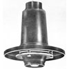
arp lantern
Lantern for war-time use. Designed to produce "comfort" lighting as specified by
BS/ARP 37. The upper and lower limits of lantern light distribution imposed by the specification
require a precision design of lantern. B.T.H. have designed and produced a lantern, bearing the
hallmark of the the B.S.I., depending on its precision and permanence of performance on the use of
die-cast parts, which are accurate to a thousandth of an inch, and cannot be deranged or distorted.
The slaient features of these lanterns are:
Easy Erection - It can be supplied completely assembled and wired to its own adaptor for
screwing into existing lamp sockets. or alternatively threaded 1½ B.S.P. for screwing direct on
to the bracket arm;
Simple Cleaning - Access can readily be obtained to every optical component;
Minimum Of Servicing - No adjustments are necessary at any time to allow for normal tolerances
in light centre lengths of lamps;
Freedom From Glare - The distribution is produced from secondary sources of low brightness.
The bare lamp is not visible from any point of view.
Three methods of support have been designed:
(1) Top caps tapped to ¾" and 1¼" BSP for screwing directly onto bracket arms;
(2) Mechanical suspension devices for holding the lantern rigidly into existing lanterns together with flexible
electrical connectors to plug into the existing lamp sockets.
(3) Rigid electrical connectors to support the lantern from lamp sockets.
25W GLS is used for mounting heights with normal spacing. 15W GLS is used for 10' mounting height with spacing of
less than 100'
|
|
???
|
15W GLS
25W GLS
|
BC
|
Top Entry
|
No Gear
|
1940 Journal
1940 Advert
1940 Journal
|
|
|
|
|
7-80 prototype lantern
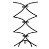
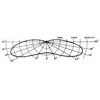 Initial prototype fluorescent lantern conceived by BTH's lighting engineers in
1945/6. Considered for Group A lighting, the typical polar diagram of light distribution to
produce the desired road surface and background brightness at wide spacing is one with
peak intensities of 5000 candles. The highest intensity obtained with reflectors and using
80W fluroescent lamps is 1500-1800 candles. So to produce intensities of 5000 candles a minimum
of three fluorescent lamps in such individual reflectors would be required. This means for a
complete fitting, a minimum of 80-watt fluorescent lamps, three in each direction to produce the
main beams and one situated beneath to fill the distribution smoothly. Such a unit would consume
700W and would have a light output of 12,000 lumens. It was not considered practical (so
it appears no physical versions were built).
|
|
7-80
|
7x80W MCF
|
14xBC
|
Side
|
Gear
|
1946 Paper
|
|
|
|
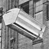
5-80 prototype lantern
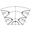
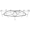 Second prototype fluorescent lantern conceived by BTH's lighting engineers in
1945/6. Considered for Group A lighting and more practical than the 7-80 lantern. This 400W unit
was built and prototypes were installed on span wires around BTH's research buildings.
|
|
5-80
|
5x80W MCF
|
10xBC
|
Side
|
Gear
|
1946 Paper
|
|
|
|
3-80 prototype lantern
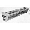
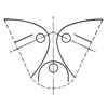
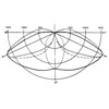 Third prototype fluorescent lantern conceived by BTH's lighting engineers in
1945/6. Takes three 80W tubular lamps. Designed to give good distribution with lantern spacings
of 80 to 100 ft. at a mounting height of 25 ft. "Anti Glare" shields were modified the normal
parabolic distribution, so light striking the underside of the glare shield is redirected to the
roadway at a useful point, giving a controlled cut-off distribution. The wide beam spread is not an
undesirable effect as kerbs, pathways, and the faces of buildings are well illuminated and enable a good
visibility at the roadside. The lantern is self-contained: chokes, starters and power factor capacitors
being built in. Access to one end only is required for relamping and starter replacement. The fitting is
weatherproof with a plastic enclosure easily removed for cleaning purposes by the operation of a toggle
catch. All the anodised aluminium reflectors are located in cast frames with both internal and external
profile supports. The alloy supports, with the main tubular spar, form the framework of the whole structure.
The roof structure and plastic enclosure are carried by this chassis and a light, strong fitting results.
Gaskets together with a very substantial deep beading ensure the fitting is watertight. The weight is
about 65 lb. The fitting is arranged for top-entry.
First installed along the High Street, Rugby in 1946. A later, identical installation was installed
along Old Bond Street, London in 1946 for the APLE Conference that September.
In the Old Bond Street and Rugby test installations, lanterns are mounted on a double wire span system
with the fittings mounted between the cables on pulleys. A very simple tractive wire device is provided
to enable the lanterns to be pulled in to the kerbside for servicing.
|
|
3-80
|
3x80W MCF
|
6xBC
|
Side
|
Gear
|
1946 Paper
|
|
|
|
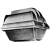
horizontal enclosed lantern / horizontal enclosed series 700 / mazdalux horizontal
For Group A lighting. A street lighting lantern which was the product of past-experience and recent post-war research.
Shown at the APLE Conference in 1946 and introduced in 1947. The main feature of the lantern are a first class optical performance and fine appearance combined with very
simple erection and maintenance. Magnetic arc control enables the standard type of vertical-burning Mercra lamp to be used
in a horizontal position. The well-known BTH principle of controlled cut-off is employed to give constant visual accommodation
and a minimum of glare. This allied to the horizontal light source, gives the maximum continuity of road brightness and optimum
seeing conditions.
Built almost entirely from silicon-aluminium alloy.
It consists of a main casting and a refractor bowl-retraining frame which is attached to the
main casting by an adjustable hinge and is locked by a quick action spring catch.
Includes a magnetic arc control to allow the standard mercury
discharge lamp to be used in a horizontal position. Has a controlled-cut-off (semi-cut-off)
distribution. Closely graded control of the light output in the vertical plane near the horizontal
ensures that glare is kept to a minimum. At the same time sufficient light is emitted up to the
horizontal to maintain continuity of visual accommodation.
|
|
SL700
|
250W/400W MA/H
|
BC
|
Side Entry
|
No Gear
|
1947 Journal
1947 Book
1950s Book
1951 Book
|
|
|
|
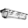
fluorescent lantern | mazdalux fluorescent
Introduced in 1947. Developed from the prototype (the 3-80) used in an experimental installation in Rugby and London.
After the experimental installation along Old Bond Street, London, constant research, coupled with experience of many
installations in other cities and towns, has led to the development of an improved lantern which is in
full production. Accommodates three Mazda 80-watt 5-ft.
fluorescent lamps. It's self-contained and compact, all the gear being assembled within the lantern and is ready wired to two
porcelain connector blocks. Each lamp has its own reflector and the circuit is so arranged that the two side lamps can
be switched off leaving the bottom lamp burning to give economy lighting after midnight.
The lantern provides illumination which preserves the
natural colours of the surroundings and is substantially free from glare. The comparatively large
light source gives very full coverage of the road and a broad even light distribution which embraces kerbs,
pathways and buildings. A pleasing feature is the absence of the colour distortion which characterises high
efficiency lighting with other types of discharge lamp.
It can be mounted directly on street standards,
or over the centre of the roadway on catenary wires. The complete absence of glare creates safer road conditions for both
driver and pedestrian. The lamps have a very low surface brightness and this, allied to a carefully designed reflector system, in a lantern
which incorporates the now well known BTH principle of controlled cut-off, results in a very high degree of visibility. Constructed from light silicon-aluminium castings with a sheet metal roof and a clear plastic cover held
in position by four toggle catches. The lantern has two hinged end covers, but it is only necessary to open one of these for lamp changing
and starter switch maintenance. Various options allow for different
mounting options. Lamps and gear can be changed by removing one of the ends.
Demonstrated at the 1947 APLE Conference in Southport (where the SL 753 on a special Concrete Utilities column was shown). Total light
output per lantern is 5700 lumens.
|
SL750
SLB750
|
3x80W MCF
|
BC
|
Side Entry
|
Gear
|
1947 Journal
1947 Conference
1947 Advert
1947 Journal
1950s Book
1951 Book
|
SL751
SLB751
|
3x80W MCF
|
BC
|
Side Entry
|
Gear
|
1947 Journal
1947 Conference
1947 Advert
1947 Journal
1950s Book
1951 Book
|
SL752
SLB752
|
3x80W MCF
|
BC
|
Side Entry
|
Gear
|
1947 Journal
1947 Conference
1947 Advert
1947 Journal
1950s Book
1951 Book
|
SL753
SLB753
|
3x80W MCF
|
BC
|
Side Entry
|
Gear
|
1947 Journal
1947 Conference
1947 Advert
1947 Journal
1950s Book
1951 Book
|
SL754
SLB754
|
3x80W MCF
|
BC
|
Side Entry
|
Gear
|
1947 Journal
1947 Conference
1947 Advert
1947 Journal
1950s Book
1951 Book
|
SL755
SLB755
|
3x80W MCF
|
BC
|
Side Entry
|
Gear
|
1947 Journal
1947 Conference
1947 Advert
1947 Journal
1950s Book
1951 Book
|
|
|
|
|
fluorescent lantern for side roads | mazdalux fluorescent
Introduced in 1947. Mentioned by G. K. Lambert in a letter to the APLE. An installation of
Group B fluorescent lanterns was installed in Rugby in August 8th 1947. The lantern was also shown at the 1947
Southport Conference but no record was found in the literature.
|
SL???
|
2x20W MCF
|
4xBC
|
???
|
???
|
1947 Journal
|
|
|
|
|
|
|
|
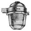
600 series (clear bowl and refractor dome)
A new series of Mazdalux Side-Entry lanterns been designed to meet the demand for a complete
range of lanterns accommodating every type and size of vertically operated Mazda and Mercra
street-lighting lamp. Introduced in 1946-7. This new "Stylised" range consists of 16 lanterns, each with the same design and appearance except for variations
in size, lampholder, reflector and glasswar. There are many advantages in this standardisation.
Lamps and glassware can be interchanged with only minor modification, and the same system of simple
maintenance can be applied to all the lanterns. For the first time, lanterns with a uniform
appearance can be installed throughout an entire city or town, the varied requirements of
such locations, as busy shopping centres, side streets and car parks all being catered for.
The shape and appearance of the lantern has been carefully designed to blend well with all types
of surroundings and to match both steel and concrete standards.
|
|
SL600
|
1500W GLS
|
GES
|
Side Entry
|
No Gear
|
1947 Book
1947 Paper
1951 Book
1950s Book
|
|
SL601
|
750/1000W GLS
|
GES
|
Side Entry
|
No Gear
|
1947 Book
1947 Paper
1951 Book
1950s Book
|
|
SL602
|
125W MAF/V
|
GES
|
Side Entry
|
No Gear
|
1947 Book
1947 Paper
1951 Book
1950s Book
|
|
SL603
|
60-150W GLS
|
BC
|
Side Entry
|
No Gear
|
1947 Book
1947 Paper
1951 Book
1950s Book
|
|
SL604
|
150-200W GLS
|
ES
|
Side Entry
|
No Gear
|
1947 Book
1947 Paper
1951 Book
1950s Book
|
|
SL605
|
80-125W MA/V
80W MAF/V
|
3BC
|
Side Entry
|
No Gear
|
1947 Book
1947 Paper
1951 Book
1950s Book
|
|
|
|
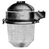
600 series (refractor bowl)
A new series of Mazdalux Side-Entry lanterns been designed to meet the demand for a complete
range of lanterns accommodating every type and size of vertically operated Mazda and Mercra
street-lighting lamp. Introduced in 1946-7. This new "Stylised" range consists of 16 lanterns, each with the same design and appearance except for variations
in size, lampholder, reflector and glasswar. There are many advantages in this standardisation.
Lamps and glassware can be interchanged with only minor modification, and the same system of simple
maintenance can be applied to all the lanterns. For the first time, lanterns with a uniform
appearance can be installed throughout an entire city or town, the varied requirements of
such locations, as busy shopping centres, side streets and car parks all being catered for.
The shape and appearance of the lantern has been carefully designed to blend well with all types
of surroundings and to match both steel and concrete standards.
|
|
SL612
|
250-400W MA/V
125W MAF/V
400W MAF/V
|
GES
|
Side Entry
|
No Gear
|
1947 Journal
1947 Book
1951 Book
1950s Book
|
|
SL615
|
80-125W MA/V
80W MAF/V
|
3BC
|
Side Entry
|
No Gear
|
1947 Journal
1947 Book
1951 Book
1950s Book
|
|
|
|
|
600 series (refractor bowl and refractor band)
A new series of Mazdalux Side-Entry lanterns been designed to meet the demand for a complete
range of lanterns accommodating every type and size of vertically operated Mazda and Mercra
street-lighting lamp. Introduced in 1946-7. This new "Stylised" range consists of 16 lanterns, each with the same design and appearance except for variations
in size, lampholder, reflector and glasswar. There are many advantages in this standardisation.
Lamps and glassware can be interchanged with only minor modification, and the same system of simple
maintenance can be applied to all the lanterns. For the first time, lanterns with a uniform
appearance can be installed throughout an entire city or town, the varied requirements of
such locations, as busy shopping centres, side streets and car parks all being catered for.
The shape and appearance of the lantern has been carefully designed to blend well with all types
of surroundings and to match both steel and concrete standards.
|
|
SL622
|
300-500W GLS
125W MAF/V
|
GES
|
Side Entry
|
No Gear
|
1947 Journal
1947 Book
1951 Book
1950s Book
|
|
SL623
|
60-150W GLS
|
BC
|
Side Entry
|
No Gear
|
1947 Journal
1947 Book
1951 Book
1950s Book
|
|
SL624
|
150-200W GLS
|
ES
|
Side Entry
|
No Gear
|
1947 Journal
1947 Book
1951 Book
1950s Book
|
|
|
|
|
600 series (opal bowl)
A new series of Mazdalux Side-Entry lanterns been designed to meet the demand for a complete
range of lanterns accommodating every type and size of vertically operated Mazda and Mercra
street-lighting lamp. Introduced in 1946-7. This new "Stylised" range consists of 16 lanterns, each with the same design and appearance except for variations
in size, lampholder, reflector and glasswar. There are many advantages in this standardisation.
Lamps and glassware can be interchanged with only minor modification, and the same system of simple
maintenance can be applied to all the lanterns. For the first time, lanterns with a uniform
appearance can be installed throughout an entire city or town, the varied requirements of
such locations, as busy shopping centres, side streets and car parks all being catered for.
The shape and appearance of the lantern has been carefully designed to blend well with all types
of surroundings and to match both steel and concrete standards.
|
|
SL630
|
1500 GLS
|
GES
|
Side Entry
|
No Gear
|
1947 Journal
1947 Book
1951 Book
1950s Book
|
|
SL631
|
750-1000W GLS
|
GES
|
Side Entry
|
No Gear
|
1947 Journal
1947 Book
1951 Book
1950s Book
|
|
SL632
|
250W-400W MA/V
125W MAF/V
400W MAF/V
|
GES
|
Side Entry
|
No Gear
|
1947 Journal
1947 Book
1951 Book
1950s Book
|
|
SL633
|
60-150W GLS
|
BC
|
Side Entry
|
No Gear
|
1947 Journal
1947 Book
1951 Book
1950s Book
|
|
SL634
|
150-200W GLS
|
ES
|
Side Entry
|
No Gear
|
1947 Journal
1947 Book
1951 Book
1950s Book
|
|
|
|
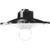
parish
The firm's Open Type Conical lantern. For Group B roads.
|
|
ST275
|
60-100W GLS
|
BC
|
Top Entry
|
No Gear
|
1950s Book
|
|
ST276
|
60-100W GLS
|
BC
|
Side Entry
|
No Gear
|
1950s Book
|
|
|
|
|
|
|
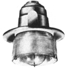
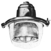
rural enclosed (clear bowl)
For Group B lighting.
|
|
ST293
|
60-150W GLS
|
BC
|
Side Entry
|
No Gear
|
1950s Book
|
|
SM296
|
80-125W MA/V
|
3xBC
|
Side Entry
|
No Gear
|
1950s Book
|
|
ST299
|
60-150W GLS
|
BC
|
Top Entry
|
No Gear
|
1950s Book
|
|
ST294
|
150-200W GLS
|
ES
|
Side Entry
|
No Gear
|
1950s Book
|
|
ST300
|
150-200W GLS
|
ES
|
Top Entry
|
No Gear
|
1950s Book
|
|
SM302
|
80-125W MA/V
|
3xBC
|
Top Entry
|
No Gear
|
1950s Book
|
|
|
|
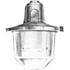
urban enclosed (clear bowl)
For Group A lighting.
|
|
ST277
|
300-500W GLS
|
GES
|
Top Entry
|
No Gear
|
1950s Book
|
|
SM278
|
250-400W MA/V
|
GES
|
Top Entry
|
No Gear
|
1950s Book
|
|
ST305
|
300-500W GLS
|
GES
|
Side Entry
|
No Gear
|
1950s Book
|
|
SM307
|
250-400W MA/V
|
GES
|
Side Entry
|
No Gear
|
1950s Book
|
|
|
|
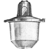
urban enclosed (refractor bowl)
For Group A lighting.
|
|
ST907
|
300-500W GLS
|
GES
|
Top Entry
|
No Gear
|
1950s Book
|
|
ST908
|
300-500W GLS
|
GES
|
Side Entry
|
No Gear
|
1950s Book
|
|
|
|
|
urban enclosed (opal bowl)
For Group A lighting.
|
|
STM279
|
300-500W GLS
250-400W MA/V
|
GES
|
Top Entry
|
No Gear
|
1950s Book
|
|
STM309
|
300-500W GLS
250-400W MA/V
|
GES
|
Side Entry
|
No Gear
|
1950s Book
|
|
|
|
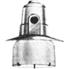
urban open (dome refractor)
For Group A lighting.
|
|
ST284
|
300-500W GLS
|
GES
|
Top Entry
|
No Gear
|
1950s Book
|
|
ST311
|
300-500W GLS
|
GES
|
Side Entry
|
No Gear
|
1950s Book
|
|
|
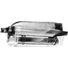
|
sodium enclosed lantern
For Group A lighting. Described as an "improved design"
in 1953. Constructed from high grade corrosion-resistant alloy.
Lamp support, side panels and an anodised aluminium
reflector are mounted to form a single optical unit. Includes
a clear Perspex cover.
|
|
SL.721
|
140W SO
|
BC
|
Top Entry
|
No Gear
|
1950s Book
1953 Advert
|
|
SL.722
|
85W SO
|
BC
|
Top Entry
|
No Gear
|
1950s Book
1953 Advert
|
|
SL.730
|
140W SO
|
BC
|
Side Entry
|
No Gear
|
1950s Book
1953 Advert
|
|
SL.731
|
85W SO
|
BC
|
Side Entry
|
No Gear
|
1950s Book
1953 Advert
|
|
|
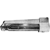
|
sodium open lantern
For Group A lighting.
|
|
SL.715
|
140W SO
|
BC
|
Top Entry
|
No Gear
|
1950s Book
|
|
SL.716
|
85W SO
|
BC
|
Top Entry
|
No Gear
|
1950s Book
|
|
SL.735
|
140W SO
|
BC
|
Side Entry
|
No Gear
|
1950s Book
|
|
SL.736
|
85W SO
|
BC
|
Side Entry
|
No Gear
|
1950s Book
|
|
|
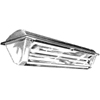
|
fluorescent lantern
Described as the "latest model" in 1953.
|
|
SLX3535
|
3x80W MCF
|
BC
|
Side Entry
|
Gear
|
1953 Advert
1953 Journal
|
|
|
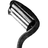
|
fluorescent lantern
For Group B lighting. Ideally suited for the lighting of residential
and shopping areas. All the auxiliary gear is included in the lantern. Can
either be mounted on a concrete bracket or a steel bracket arm. Used for
the side-street lighting in Stevenage New Town.
|
|
SL.3500
|
2x40W MCF
|
BC
|
Top Entry
|
Gear
|
1950s Book
1953 Advert
|
|
|
|
|
horizontal sodium open lantern
For Group A lighting.
|
|
??
|
85W SO
|
BC
|
Side/Top Entry
|
No Gear
|
1953 Journal
|
|
??
|
140W SO
|
BC
|
Side/Top Entry
|
No Gear
|
1953 Journal
|
|
|
|
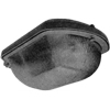
sapphire
Introduced in 1953. Can be fitted with a magnetic deflector if
required. Light distribution is of the "non-cut-off medium angle beam"
type as defined in BSCP1004:1952. Also complies with Street Lighting Lanterns
BS 1788:1951.The glass bowl has diffusing ripples which are self-cleaning in
the rain. Made from corrosion-resistant casting LM6M alloy.
|
|
SL???
|
250-400W MA/H
|
ES
|
Side Entry
|
No Gear
|
1953 Advert
1953 Journal
1955 Advert
|
|
|
|
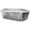
amber
For Group A lighting. Gives a non-cut-off medium-angle
beam. Gear optional.
|
|
??
|
85W-140W SO
|
BC
|
Side Entry
|
No Gear
|
1955 Advert
|
|
??
|
85W-140W SO
|
BC
|
Side Entry
|
Gear
|
1955 Advert
|
|
|
|
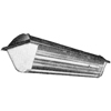
diadem lantern
For Group A lighting. With built-in gear for either
Switch-Start or Instant-Start lamps.
|
|
???
|
??? MCF
|
BC
|
Side Entry
|
Gear
|
1955 Advert
|
|


